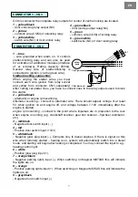
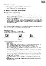
background image

EN 


Changing PIN code 

PIN code is set as the factory default code (11). PIN code must be inserted to enter Valet 
mode after turning key on/off 3 times if you have already selected “PIN code ON” from 
optional table. 
 
 
Procedures of change PIN code from the factory default code 11 to owner’s own code 

1. System is disarmed. 
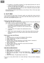
2.  Maintain the conditions of the trunk and the door being opened. 
3.  Turn the key on/off 3 times. Lights will flash once. Siren makes a long beep. 
4.  Push the button on RPS as many times, as your first number (1-9) is. Intervals 

between the click/pushes must not be longer than 1.5 sec.  

5.  Siren beeps once. Lights will flash once.  
6.  Push the button on RPS as many times, as your second number (1-9) is.  
7.  Siren beeps twice. Lights will flash twice. 
8. Press button 

IV

 on remote for authentication. Siren beeps three times and lights will 

flash three times. 


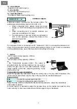
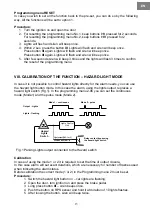
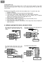
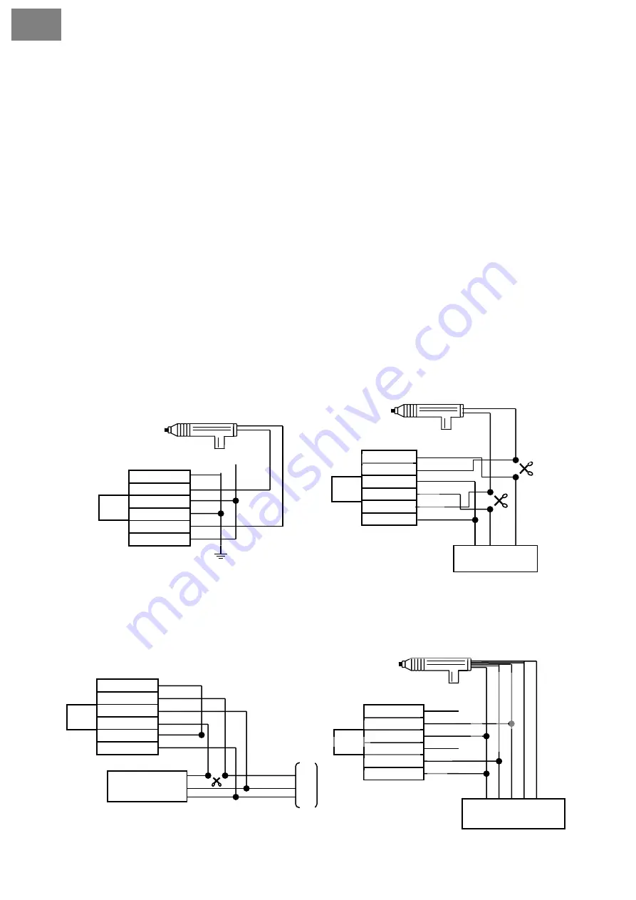
XI. WIRING DIAGRAM FOR DOOR LOCKING SYSTEM 


Fig.1 Original built-in central power lock with a switch 

inside the doors. A motor at the control level  are 

required.  

Fig.2 Original central power lock & electric power lock 
switch inside the front doors.. 


16


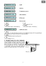
Fig.3 Original built-in central power lock & using 
compressor to control the switch. Note: Active time 4 

sec.  

Air-comp

ressor 


Unlock  

Lock  

Electric motor switch 

Main line  

NC1 

NC2 

COM1 

NO1

COM2


NO2 

yellow/black 

yellow 

yellow/white 

green/black 

green 

green/white


CN3 

+12V 

Unloc

k


Lock  

yellow/black 

yellow 

yellow/white 

green/black 

green/white


green 


NC1 

NC2 

COM1 

NO1

COM2


NO2 

CN3 

CN3

Front door switch


yellow/black

yellow

yellow/white

green/black

green/white

green

NC1

NC2

COM1 

NO1

COM2

NO2

Unloc

k


Lock  

+12V 

C

o

nt
a

c

t -

 lo

ck
ed
 

Con

tact - 

u

n

loc

ked 

yellow/black 

yellow

yellow/white 

green/black

green/white

green


NC1

NC2

COM1 

NO1

COM2


NO2 

Original built-in control 

unit. 

Fig.4 Original built-in central power lock


L

o

c

k

e

d


Grou

nd  

U

n

lo

c

k

e

d


CN3

Summary of Contents for M870AS

Page 1: ...MAGICAR M870AS EN Car alarm with two way remote and remote start system Installation guide...

Page 2: ...English EN...

Page 3: ...al functions 10 Programming menu No 1 11 Programming menu No 2 12 VIII CALIBRATION OF THE FUNCTION HAZARD LIGHT MODE 13 IX VALET MODE 14 Entering valet mode without a pin code 14 Entering valet mode w...

Page 4: ...II PLACING When fitting each component consider properly the right place for a microwave interior sensor if fitted Since this sensor is working on magnetic principle it is very sensitive to a magnetic...

Page 5: ...carried out in a safe place in an appropriate distance from busy roads and on a flat surface Before the installation get all necessary equipment ready e g servos diodes relays etc When receiving a car...

Page 6: ...blocking wire 3 green Ignition Output connect to the switchboard to the 12V wire when ignition on Supplies power to the starter wiring 4 black Chassis Grounding grounding It must be firmly fixed to t...

Page 7: ...tween 7 14V immediately after the engine is started engine rpm scanning connect to the point where impulses are in proportion to the revs when engine is running e g crankshaft scanner gear box scanner...

Page 8: ...y use a 30A fuse when connecting to the relay 1 yellow AUX1 output rating capacity 250mA 2 yellow white AUX2 output rating capacity 250mA or the Transponder by pass control The output is grounded when...

Page 9: ...eans the sensor is mains operated 2 white input of additional sensor reacting on 3 red power supply of 12 V V CONNECTING OF CLUTCH SENSOR This connecting is needed in case the car when starting requir...

Page 10: ...beep once to confirm the access of the Programming mode 3 Within 2 seconds of the step 1 press button IV as many times as is the order number of the function you want to set After each pressing of bu...

Page 11: ...rvation mode set up For reservation mode setting to carried out transmission must be in a neutral position emergency brake pulled up with the engine running By turning ignition off the engine remains...

Page 12: ...t Off 0 C 5 C 10 C 2 13 Arm disarm by OEM remote control Enabled Disabled Function explanation 2 01 Impulse time set up for trunk output 2 02 Impulse time set up for door lock 2 03 Impulse time set up...

Page 13: ...arm needs you can use the hazard light button mode In this case the alarm using the lights output replaces a hazard light switch Fig 1 In the programming menu 2 06 you can set the continuous mode Mode...

Page 14: ...most vehicles this position is located two clicks forward from the Off position 2 Turn the ignition off The lights on the dashboard should be turned off 3 Steps 1 and 2 must be repeated for a total of...

Page 15: ...ons for primary setup of security code Function in Programming menu 1 04 must be set Disarmed ignition on Doors opened engine off Programming of security code 1111 9999 1 Ignition is on 2 Open the doo...

Page 16: ...ree times and lights will flash three times XI WIRING DIAGRAM FOR DOOR LOCKING SYSTEM Fig 1 Original built in central power lock with a switch inside the doors A motor at the control level are require...

Page 17: ...2 yellow 1 white 1 purple fuse 15A 2 purple 3 white 4 grey 5 grey white CN 2 Light NO Light NO 12V output to siren Trunk COM Trunk N O Common wire Trunk wire Trunk solenoid Unlock NC Unlock NO Unlock...

Page 18: ...parts as well as onto the box Warning Any alternations or additions to the system will automatically invalidate the installation certificate INSTALLATION CERTIFICATE I the undersigned as a profession...

Reviews: