EN
+12V
Signal Light wire
+ -
+ -
Common wire
- +
MAGICAR
9 grey/black
8 orange
7 orange/black
6 white
5 white/black
4 red
3 red/black
2 yellow/black
1 blue
CN 1
RPS sensor
Shock sensor
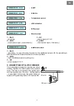
LED signaling
Output to
accessory
Output to ignition
Trunk trigger input (-)
Output to starter 12V
Siren
fuse 40A
Parking light input (+)
Parking light input (-)
Glow plug input for diesel (+)
Glow plug input for diesel (-)
Door switch input (+)
Door switch input (-)
Alt/Rev sensing input
Output to starter-kill (-250mA)
Ground
Ver. 1.00
5 red
6 red/white
12V constant
Light (COM)
4 black
3 green
2 yellow
1 white
1 purple
fuse 15A
2 purple
3 white
4 grey
5 grey/white
CN 2
Light (NO)
Light (NO)
12V output to siren
Trunk (COM)
Trunk (N.O)
Common wire
+ -
Trunk wire
- +
Trunk solenoid
Unlock (NC)
Unlock (NO)
Unlock (COM)
Lock (NC)
5 green
6 green/white
Lock (COM)
Lock (N.O)
4 green/black
3 yello/white
2 yellow
1 yello/black
CN 3
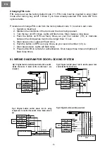
See wiring
diagram for door
locking system
Page 16
fuse 10A
fuse 15A
fuse 15A
12 light blue/black
11 black/white
10 brow/black
Emergency brake input (-)
Foot brake input (+)
Hood trigger input (-)
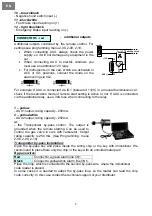
Temperature sensor
+12V
Antenna
M
A
G
ICAR
1 ye
llow
AUX 1 (-250mA)
AUX2 / Bypass (-250mA)
2 ye
llow/white
Additional/Ultrasonic
sensor
CN 11
CN 10
CN 4
CN 7
CN 6
CN 12
CN 9
CN 8
UART
CN 5
Optional
| red
+
|
white input
|
black -
|
Battery
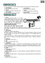
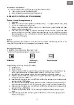
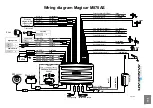
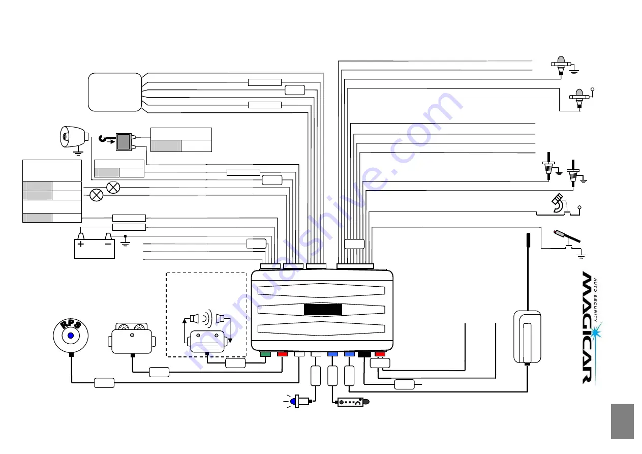
Wiring diagram Magicar M870AS


