background image

EN 


6

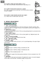
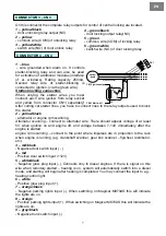
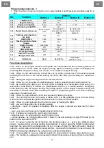
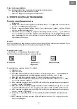
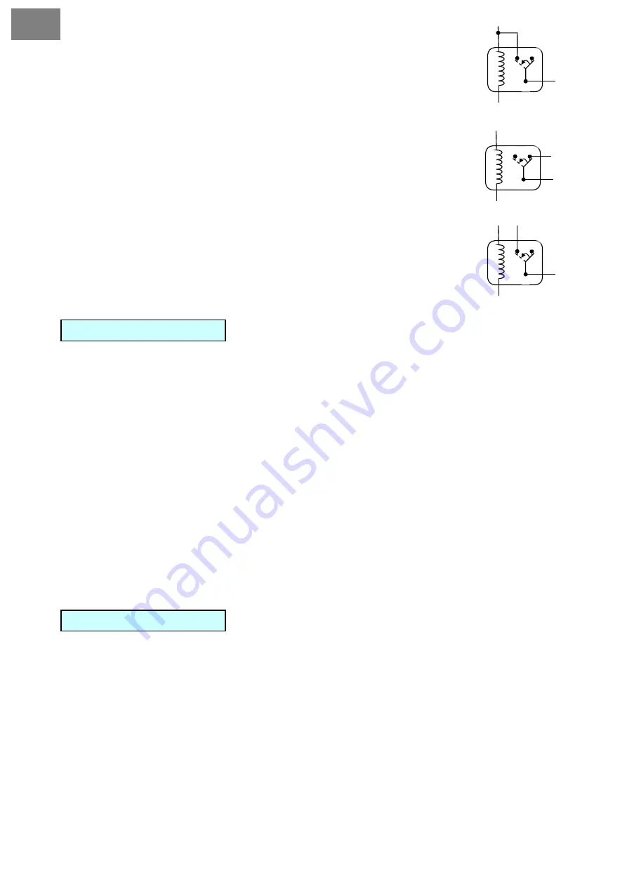
If you want to change the signal polarity (-) to (+) 

87 

30 

87a 

85 

86 

+12V 

output (+) 

impuls (-) 

E.g.: When AUX is installed, a relevant device is operating on (+). 


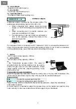
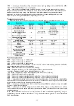
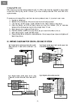
If you want to disconnect two wires by a (-) signal 

+12V 

E.g.: With a (-) signal, lines A and B are cut off. Use this when a starter-
blocker is installed. 
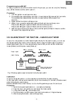
87  87a 


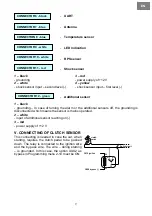
If you want to connect shortly two wires by (-) signal. 

E.g.: Mostly used for installing alarm gas relays. 


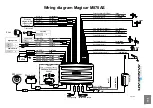
IV. WIRING ARRANGEMENT 


1 – white – Accessory Output 

- connect to the switchboard (to the +12V wire) with the key in the ACC position. If the 
engine is on, there is no voltage in this wire. It is possible to use the wire to supply A/C or 
heating system.  

2 – yellow- Starter Output 

- connect to the switchboard (to the +12V wire during starting) Mustn’t be connected to the 
starter-blocking wire.   

3 – green- Ignition Output 

- connect to the switchboard (to the +12V wire when ignition on). Supplies power to the 
starter wiring. 

4 – black – Chassis Grounding  


- grounding (-). It must be firmly fixed to the car body. 

5 – red - +12V Power supply 

- power supply, connect to +12V.  

6 –red/white – Lights 
- 

This is a line for lights output, connect on +12V or earth depending on the type of lights 

power supply. 


1 – purple   

- Signal lights output. It switches voltage in red/white wire CN1.


2 – purple   

- Signal lights output. It switches voltage in red/white wire CN1.


3 – white 

-  siren output. When activated pr12V. 

4 – grey 

- common wire for supply of the trunk opening mechanism. Can be connected to the +12V 
wire or earth. 

5 – grey/white 

- relay output for trunk opening mechanism (if supplied with a servo or an electromagnet) 
can be used to open the trunk. It switches voltage in the grey CN2.  
 

CONNECTOR 1 – CN1 

CONNECTOR 2 – CN2 

30 

86 

line A 

line B 

85 

impuls (-) 

+12V 

87 

30 

87a 

85 

line A 

line B 

86 

impuls (-) 

Summary of Contents for M870AS

Page 1: ...MAGICAR M870AS EN Car alarm with two way remote and remote start system Installation guide...

Page 2: ...English EN...

Page 3: ...al functions 10 Programming menu No 1 11 Programming menu No 2 12 VIII CALIBRATION OF THE FUNCTION HAZARD LIGHT MODE 13 IX VALET MODE 14 Entering valet mode without a pin code 14 Entering valet mode w...

Page 4: ...II PLACING When fitting each component consider properly the right place for a microwave interior sensor if fitted Since this sensor is working on magnetic principle it is very sensitive to a magnetic...

Page 5: ...carried out in a safe place in an appropriate distance from busy roads and on a flat surface Before the installation get all necessary equipment ready e g servos diodes relays etc When receiving a car...

Page 6: ...blocking wire 3 green Ignition Output connect to the switchboard to the 12V wire when ignition on Supplies power to the starter wiring 4 black Chassis Grounding grounding It must be firmly fixed to t...

Page 7: ...tween 7 14V immediately after the engine is started engine rpm scanning connect to the point where impulses are in proportion to the revs when engine is running e g crankshaft scanner gear box scanner...

Page 8: ...y use a 30A fuse when connecting to the relay 1 yellow AUX1 output rating capacity 250mA 2 yellow white AUX2 output rating capacity 250mA or the Transponder by pass control The output is grounded when...

Page 9: ...eans the sensor is mains operated 2 white input of additional sensor reacting on 3 red power supply of 12 V V CONNECTING OF CLUTCH SENSOR This connecting is needed in case the car when starting requir...

Page 10: ...beep once to confirm the access of the Programming mode 3 Within 2 seconds of the step 1 press button IV as many times as is the order number of the function you want to set After each pressing of bu...

Page 11: ...rvation mode set up For reservation mode setting to carried out transmission must be in a neutral position emergency brake pulled up with the engine running By turning ignition off the engine remains...

Page 12: ...t Off 0 C 5 C 10 C 2 13 Arm disarm by OEM remote control Enabled Disabled Function explanation 2 01 Impulse time set up for trunk output 2 02 Impulse time set up for door lock 2 03 Impulse time set up...

Page 13: ...arm needs you can use the hazard light button mode In this case the alarm using the lights output replaces a hazard light switch Fig 1 In the programming menu 2 06 you can set the continuous mode Mode...

Page 14: ...most vehicles this position is located two clicks forward from the Off position 2 Turn the ignition off The lights on the dashboard should be turned off 3 Steps 1 and 2 must be repeated for a total of...

Page 15: ...ons for primary setup of security code Function in Programming menu 1 04 must be set Disarmed ignition on Doors opened engine off Programming of security code 1111 9999 1 Ignition is on 2 Open the doo...

Page 16: ...ree times and lights will flash three times XI WIRING DIAGRAM FOR DOOR LOCKING SYSTEM Fig 1 Original built in central power lock with a switch inside the doors A motor at the control level are require...

Page 17: ...2 yellow 1 white 1 purple fuse 15A 2 purple 3 white 4 grey 5 grey white CN 2 Light NO Light NO 12V output to siren Trunk COM Trunk N O Common wire Trunk wire Trunk solenoid Unlock NC Unlock NO Unlock...

Page 18: ...parts as well as onto the box Warning Any alternations or additions to the system will automatically invalidate the installation certificate INSTALLATION CERTIFICATE I the undersigned as a profession...

Reviews: