
EN
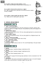
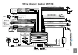
CONNECTOR 3 – CN3
On this connector the complete relay outputs for control of central locking are located.
7
1 – yellow/black
- door unlocking relay output (NC)
2 – yellow
- common wire (COM) of unlocking relay
3 – yellow/white
- switch wire (NO) of door unlock relay
1 – blue
- wire grounded when alarm on. It controls
starter-blocking relay and can also be used
for activation of additional modules (interface
of el. windows). Rating capacity 250mA.
Second relay wire of starter-blocking is
connected to ignition. (via the green wire).
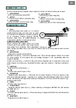
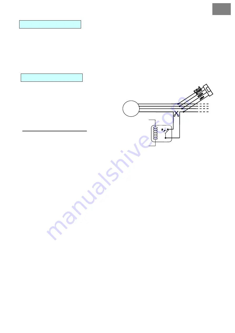
Starter-blocking connection:
When untying the starter wires you must
connect each wire (yellow from relay socket
and yellow from connector CN1) separately!
After cutting car starter lines, you have to connect lines to the relay outputs used to block
the starter.
2 – yellow/black
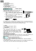
- alternator or engine rpm scanning.
Alternator scanning
– connect to alternator wire. There should appear voltage of at least
5V when ignition on and engine off, and voltage between 7-14V immediately after the
engine is started.
engine rpm scanning
– connect to the point where impulses are in proportion to the revs
when engine is running (e.g. crankshaft scanner, gear box scanner – flywheel, distributor,
etc.)
3 – red/black
- Negative door switch input ( - )
4
–
red
- Positive door switch input (+12V)
5 – white/black
- Negative glow plug input (-). Connects only to diesel engines. If there is signal on this
wire when remotely started – heating is on, system will automatically switch into a diesel
mode, and starting will begin after heating is completed. You may connect the input to e.g..
heating control light.
6 – white
- Positive glow plug input (+).
7 – orange/black
- Negative parking lights input (-). When switching on Magicar M870AS this will indicate
the lights are on.
8 – orange
- Positive parking lights input (+). When switching on Magicar M870AS this will indicate the
lights are on.
9 – grey/black
- Negative trunk switch input (-)
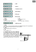
CONNECTOR 4 – CN4
87 87a
86
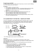
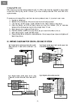
Start line circuit
CN1-3 ignition output
CN4-1 Starter-kill
CN1
Cut off
ť
switch-
board
4 – green/black
- door locking output relay(NC)
5 – green
- common wire (COM) of locking relay
6 – green/white
- switch wire (NO) of door locking relay
30
85


