

EN
10 – brown/black
- Negative hood switch input (-)
11 –black/white
- Foot brake input reacting on (+)
12 – light blue/black
- Emergency Brake input reacting on (-)
8
-
additional outputs
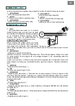
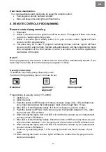
CONNECTOR 5 - red
Additional outputs controlled by the remote control. For
settings see programming menu 2-08, 2-09, 2-10.
•
When connecting AUX, always check the power
supply, so it will not damage any equipment in the
car.
•
When connecting AUX to electric windows you
must use an additional 12V relay.
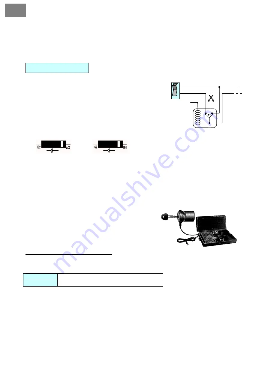
•
For instruments (in the car), which are activated in
ACC or IG1 positions, connect the diode on the
alarm wiring via IG2.
For example:
If AUX is connected via IG1 (instead of +12V) in a manual transmission car,
check if the reservation mode of remote start setting is active or not. If AUX is connected
via the additional relay, use a 30A fuse when connecting to the relay
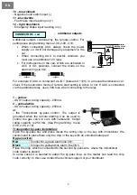
1 – yellow
- AUX1 output, rating capacity - 250mA.
2 – yellow/white
- AUX2 output, rating capacity - 250mA.
or
- the Transponder by-pass control. The output is
grounded when the remote starting. Can be used to
control the gas valve in cars with carburetor. Output
rating capacity is 250 mA. (See Programming menu
2-08, 2-09, 2-10)
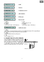
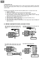
Transponder by-pass installation:
Open the by-pass box and place inside the wiring chip or the key with immobilizer. We
recommend to place there only the chip or the key with an unmilled metal part!
By-pass wires:
Red
Connect to a green alarm line CN1
Black
Connect to yellow/white alarm line CN5
Place the loop, which is connected to the second by-pass wire, where the immobilizer
code reader is placed.
In some cases it is needed to adapt the by-pass loop, so the reader can read the chip
code correctly. In this case contact the technical support of your distributor.
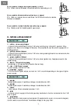
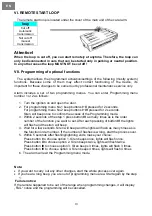
87 87a
Switching circuit
86
+12V
AUX (-)
Cutt off
switch
30
85


