-22-
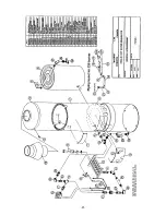
HWG20 & HWG40 Wiring
24 volt electronic ignition systems
(intermittent pilot)
Wiring-diagram.cad
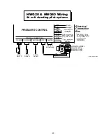
HWG20 & HWG40 Wiring
24 volt standing pilot systems
Damper
jumper plug
HWG40 & HWG20
24V Gas Valve
#HWG40-16x24
#HWG20-16x24
Flue
Sensor
TH
TR
O
F
F
PI
LO
T
TH-TR
O
N
Temp
Sensor
Flow
Switch
PROSAFE II
CONTROL
TERMINAL CONNECTIONS
FLUE SENS TEMP SENS
FLOW SW
OUTPUT DAMPER
brown
black
black*
black*
purple
purple
blue
grey
yellow
Refer to manual for
wiring of purple, blue,
grey, yellow & white
*Duplicate black
wires for
convenience
Electrical
Connection
Box
24vac
supply**
IMPORTANT: If the
24 vac supply is to be
earth grounded, earth
ground must be
connected to
the black wire.
**
red
green
black
HWG-AD10N (HWG40) or
HWG-AD7N (HWG20)
Automatic Vent Damper (optional)
If not installed then Damper jumper
plug must be installed.
Flue
Sensor
Temp
Sensor
Flow
Switch
Electronic Ignition Control
#HWG-125
Pilot Sensor/Ignitor
high voltage lead
Burner Bar Ground
M
V
M
V
/P
V
P
V
G
N
D
2
4
V
G
N
D
2
4
V
T
H
-W
S
P
A
R
K
PROSAFE II
CONTROL
TERMINAL CONNECTIONS
FLUE SENS TEMP SENS
FLOW SW
OUTPUT DAMPER
brown
black
24vac
supply**
black*
black*
purple
purple
blue
grey
yellow
white***
Refer to manual for
wiring of purple, blue,
grey, yellow & white
*Duplicate black
wires for
convenience
Electrical
Connection
Box
black
red
green
HWG40
24V Gas Valve
#HWG40-16x24R
TR
TH
HWG20
24V Gas Valve
#HWG20-16x24R
1
2
3 4
IMPORTANT: If the 24 vac supply
is to be earth grounded, earth
ground must be connected to
the black wire.
**
***On some heaters
this wire may
be brown
white***
***On some heaters
this wire may
be brown
Summary of Contents for HWG20
Page 2: ...this page was intentionally left blank...
Page 4: ...this page was intentionally left blank...
Page 23: ...20...
Page 24: ...21...

