-5-
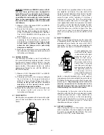
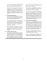
If the water outlet of the
heater is to be
connected to rigid piping
that is to be distributed
through a facility, it is
recommended that a
short “snubber” hose be
used to connect the
water outlet of the
heater to the rigid
piping. The “snubber”
hose must be rated for
the operating pressure
of the pump and the
water outlet temperature
of the heater.
The plumbing from the water outlet should be
properly sized for the flow rate desired in order to
prevent pressure loss. As with inlet plumbing,
teflon tape should be used to seal all joints.
4.10 ELECTRICAL CONNECTIONS
The heater is supplied with an electrical
connection box where all electrical connections
are to be made.
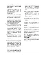
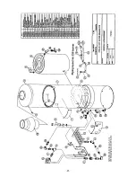
Figure 4.10.1
Remove the 4 screws holding the flat lid cover to
the front of the electrical connection box as shown
in figure 4.10.1 The inside of the electrical
connection box has been divided into 2 sides. The
right hand side is for the 120 volt connection to a
transformer (if required), while the left hand side is
for all low voltage connections.
There are two typical wiring configurations for the
HWG40 heater. The first configuration is utilized
when the heater is installed in conjunction with a
Magikist control panel such as the CPTX timed
shutdown control panel. For this configuration, all
connections including power for the heater are
made between the heater and the control panel.
(the only exception to this is the optional power
venter). Please refer to the wiring diagram
supplied with the Magikist control panel for the
most up to date instructions on wiring the heater
to the control panel. For connections to the power
venter, refer to the power venter wiring
instructions later on in this section.
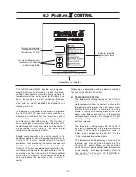
The second wiring configuration is used when
installing the heater without a Magikist control
panel. If 24VAC is not available you will need to
mount the supplied transformer to the electrical
connection box and wire the heater according to
method 1 in figure 4.10.2. If the heater is being
added to a system where an existing transformer
has available 24VAC at a minimum of 40VA, you
may wish to simply tap off this transformer and
wire the heater according to method 2.
Even though in most cases it is not recommended
that the 24vac supply be earth grounded, if the
24vac supply is to earth grounded then the earth
ground MUST be connected to the black wire.
The EXTERNAL CONTROL connections (purple
wires) provide an external means of enabling or
disabling the heater. The EXTERNAL CONTROL
connections are wired together at the factory,
thereby always enabling the heater. For
installations that utilize a Magikist control panel,
follow the wiring diagram supplied with the control
panel for the EXTERNAL CONTROL connections.
For installations that do not utilize a Magikist
ELECTRICAL
CONNECTION BOX
WITH FLAT LID
REMOVE THESE
4 SCREWS
ELECTRICAL
CONNECTION BOX
WITH ELECTRONIC
IGNITION MODULE
& FLAT LID
P
RO
S
AFE
II
CONTROL
P
RO
S
AFE
II
CONTROL
REMOVE THESE
4 SCREWS
WATER
OUTLET
PROSAFE II CONTROL
Flue
Sensor
Temp
Sensor
Flow
Switch
WATER
INLET
PROSAFE II CONTROL
Flue
Sensor
Temp
Sensor
Flow
Switch
FLOW
SWITCH
PROSAFE II CONTROL
Flue
Sensor
Temp
Sensor
Flow
Switch
24VAC
SUPPLY
ELECTRICAL
CONNECTION BOX
black
brown
purple
blue
black*
black*
purple
grey
yellow
white**
ELECTRICAL
CONNECTION BOX
120V to 24V
Transformer
120VAC
SUPPLY
black
white
black
brown
purple
blue
black*
black*
purple
grey
yellow
white**
ELECTRICAL
CONNECTION BOX
METHOD 1
METHOD 2
ELECTRICAL
CONNECTION BOX
Field wiring shown in dashed lines.
Duplicate black wires for convenience.
On some heaters this wire may be brown.
*
**
Figure 4.9.1
Figure 4.10.2
Summary of Contents for HWG20
Page 2: ...this page was intentionally left blank...
Page 4: ...this page was intentionally left blank...
Page 23: ...20...
Page 24: ...21...


