1-800-MAGLINE (624-5463)
Page 33 www.magliner.com
CooLift
®
+/- 1 in.-lbs.
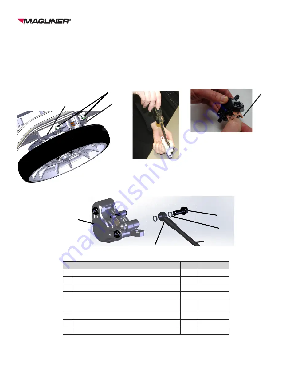
15) Position the calipers (D) within the caliper mounts and lightly hand tighten the mounting screws
(A). NOTE: Do not use the wrench on them until the calipers have been aligned or damage to the
brake disc could result.
16) With the caliper mounting screws (A) lightly hand tightened, engage the holding brake to correctly
position the caliper (D) orientation to the brake disc (C). Then the screws may be tightened using
the 5mm Allen wrench.
17) Bleed the brake system (see Bleeding the Brakes).
Quantities listed are for one side of the CooLift
Compressing the piston
A
C
Item
Qty. Part Number
A Hex socket head cap screw - M6 x 20mm
2
80003
B Pair of brake pads with leaf spring
1
309594
C Brake disc
1
309050
D Caliper assembly
1
309595
E Caliper brake line assembly (includes F, G
and H)
1
309145
F
Banjo bolt
1
80135
G
O-rings
2
n/a
H
Banjo fitting on brake line
1
n/a
D
Figure 1
Figure 2
Figure 3
E
D
F
G
Figure 4
E
H
Removing/Inserting the pads
B


