background image

24

(page intentionally left blank)

Summary of Contents for MAGMA FOG 1500 IP

Page 1: ...User Manual MAGMA FOG 1500 IP...

Page 2: ...es to any persons and direct or indirect economic loss associated with the use or reliance of any information contained within this document and or as a result of the improper unsafe insufficient and...

Page 3: ...6 Safety Guidelines 7 Overview 9 Installation 10 Optional Magfly Wireless Card 11 Torque Setting 12 Torque Scew Locations Specs 13 Setup 14 Control Panel 15 System Menu 16 DMX Channels 19 RDM Paramete...

Page 4: ...ash Please recycle whenever possible BOX CONTENTS Power Cable x1 CUSTOMER SUPPORT Contact MAGMATIC customer service for any product related service and support needs Also visit forums elationlighting...

Page 5: ...r manual D This is not a service contract and this warranty does not include any maintenance cleaning or periodic check up During the periods as specified above Magmatic Effects will replace defective...

Page 6: ...ht pre paid and insured to MAGMATIC in Los Angeles CA or a MAGMATIC Authorized Service Center The RMA number must be clearly written on the outside of the return box and a brief description of the pro...

Page 7: ...CLASS 1 FIXTURE MUST BE PROPERLY GROUNDED THERE ARE NO USER SERVICEABLE PARTS INSIDE THIS UNIT DO NOT ATTEMPT ANY REPAIRS YOURSELF DOING SO WILL VOID YOUR MANUFACTURER S WARRANTY DAMAGES RESULTING FRO...

Page 8: ...ce if the power cord has been frayed crimped and or damaged Replace any damaged power cords with new cords of the same power rating Do not remove or break off the ground prong from the electrical cord...

Page 9: ...VIEW Fog Outlet Hanging Bracket MagFly Input Cover Fluid Tank Carry Handle Carry Handle Safety Cable Loop Display Cover Touch Screen Display Remote In DMX In Out Power In 20A Breaker Bracket Knob Air...

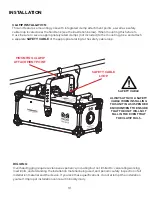
Page 10: ...e loop RIGGING Overhead rigging requires extensive experience including but not limited to calculating working load limits understanding the installation material being used and periodic safety inspec...

Page 11: ...or ordering information see ACCESSORIES section on page 23 1 Locate the MagFly input cover and remove all 8 screws with a phillips screw driver 2 Insert up to 2 MagFly receiving cards into the card sl...

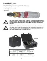
Page 12: ...URE USING THE IP TESTER CONTACT SERVICE SERVICE FOR MORE DETAILS IP PRESSURE TESTING PARAMETERS Low Pressure Limit High Pressure Limit Steady Hold Time 3 04PSI 21kPa 4 49PSI 31kPa 30 seconds CAUTION T...

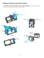
Page 13: ...cm 5 5 0 5 kgf cm Screw 8pcs Screw 4pcs Screw 22pcs Screw 8pcs Hexagonal steel column 4pcs Screw 10pcs Waterproof connector 3pcs Waterproof connector 3pcs Waterproof vent valve Waterproof connector W...

Page 14: ...0L Never run the unit on anything other than approved MAGMATIC branded fluid as doing so can result in severe damage to your device 5 Screw the tank cap back onto the fluid tank Be careful not to pinc...

Page 15: ...e the fixture s main menu will be displayed see Main Menu Screen below Press the main menu icon you would like to access Use the ENTER button to access sub menus and use the UP and DOWN buttons to mak...

Page 16: ...gfly Transmit On LCD Set Screen OFF Never 10s 40s 1min 2min 5min 10m in 20min Display Blackout Time Magfly Set Magfly Channel 0 14 Magfly Channel Setting Magfly On Off Magfly Activation No Fluid On Of...

Page 17: ...gApp MagRF Slot 2 Status Last Control LCD_auto LCD_manual DMX MagApp MagRF MagRemote Error Current Control Status MagRemote State YES NO Remote Control Status MagApp Connect Null Phone Route No Wifi C...

Page 18: ...nd 4 bars being strongest Icon appears when MagRF module is connected Note that the icon will only appear if an RF signal exists Icon appears when MagRemote is connected Icon indicates that the fluid...

Page 19: ...NCTIONS VALUES MAGMATIC MAGMA FOG 1500 IP DMX TRAITS 1 CH 2 CH 4 CH VALUES FUNCTION 1 1 FOG 000 005 OFF 006 255 ON 1 2 2 VOLUME 0 255 1 100 3 DURATION 000 005 0s 006 255 1s 250s 4 INTERVAL 000 005 0s...

Page 20: ...ler can then use its SET command to modify settings that would typically have to be changed or viewed directly via the unit s display screen including the DMX Address DMX Channel Mode and Temperature...

Page 21: ...21 DIMENSIONAL DRAWINGS 16 18 in 411mm 12 32in 313mm 10 51in 267mm 25 51in 648mm 11 73in 298mm 13 26in 337mm...

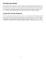
Page 22: ...require service Please contact Magmatic Effects for assistance contact information on page 4 CLEANING MAINTENANCE When storing your device be sure to store in a cool area Cover the device so that dus...

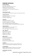
Page 23: ...DMX Transceiver Optional MAGRF Wireless and MAGREMOTE Wired Remotes CONNECTIONS Locking 5pin XLR Connector DMX In Out IP65 Locking Power Connector In With Wired Digital Communication Network SIZE WEI...

Page 24: ...24 page intentionally left blank...

Reviews: