BLUEPIRAT RAPID | USER MANUAL/
page 14 of 67
6
Control elements at the front side
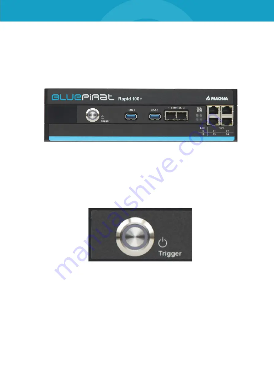
The next section describes the usage of the controls and connectors of the BLUEPIRAT Rapid.
The
BLUEPIRAT Rapid
provides two
10 Gbit/s
Ethernet interfaces (ETH #1 / TSL and ETH #2
/ TSL) on the front side.
The
[ON / Trigger]
key, the status LEDs
STATE / ACTIVE / Diagnostics / Memory
, the 2
USB
3.0
connections and the four
1 Gbit/s
interfaces are also located there.
Figure 6.1: BLUEPIRAT Rapid 100+ (D-sample)
6.1
ON / Trigger button
Use the
[ON / Trigger]
button to switch on the logger when it is connected to the power supply
and in standby mode.
Figure 6.2: BLUEPIRAT Rapid | ON / Trigger button
Important events can be marked with the
[ON / Trigger]
button. If you press the key, the logger
saves the current time as a marker. It is possible to configure the logger to take an action like
sending a CAN message too. In addition, it is possible to define messages that initiate triggers.
A debounce takes place, which allows the setting of max. ten triggers every 2 seconds.
When downloading the data, the client displays all triggers in an overview. In this overview you
can select which data should be transferred around the marker.


