background image

6

BEFORE INSTALLING THE UNIT

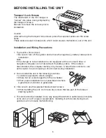
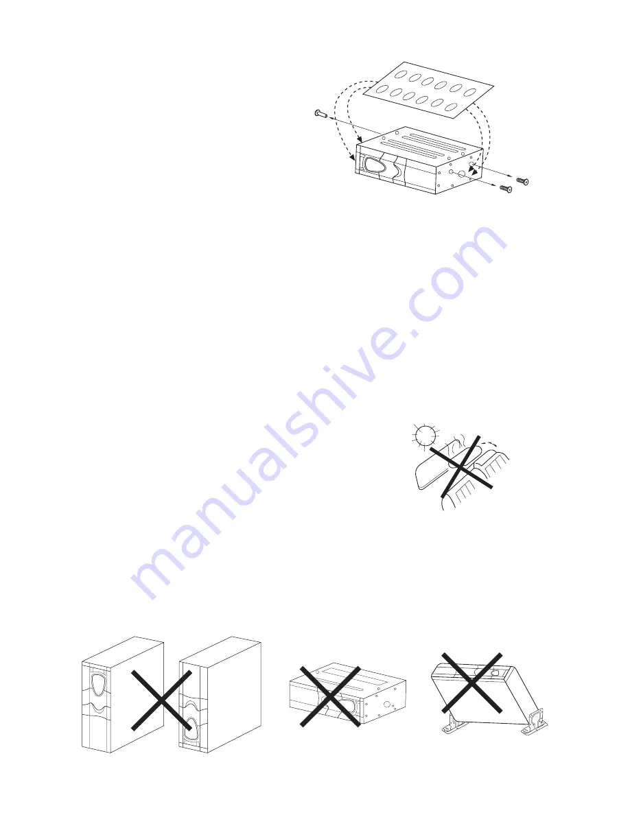
Transport Lock Screws

The mechanism in the CD changer is
“locked” into place during shipment by
the transport screws.
Be sure to remove the screws prior to
installation.

Caution
After removing the transport lock screws, place the supplied seals over the screw
holes.
These seals are used to keep dust, which could cause a malfunction, out of the unit.

Installation and Wiring Precautions

1. To prevent a short-circuit.

• Be sure to turn off the ignition and remove the negative (–) battery cable prior to

installation.

Note
If the changer is to be installed in a car equipped with an on-board drive or 
navigation computer, do not disconnect the battery cable.  If the cable is 
disconnected, the computer memory may be lost.  Under these conditions, use 
extra caution to avoid causing a short circuit during installation.

2. Do not install the unit in the following locations.

• Locations exposed to direct sunlight.
• Where hot air is discharged from the car-heater.
• When proper installation is not possible and where

a great deal of vibration is generated.

3. • Be sure to use the supplied brackets and screws.

• When installing the unit, do not use any screws that are part of the brake or 

steering system.

4. This unit cannot be installed in any way except that which is authorized (on its side,

on its end, at a 45

°

 angle or suspended).  Installing it with its side facing down 

upside down can cause malfunctioning.

Summary of Contents for EAX540

Page 1: ...Installation and Operations Manual R U S Patent No D486 815 EAX540 COMPACT DISC AUTO CHANGER...

Page 2: ...ground systems The unit cannot be used on 24 volt or positive ground systems The unit may not operate correctly in extremely hot or cold temperatures The unit is equipped with a built in self protect...

Page 3: ...ght 2 First check that the magazine with the discs has its top side facing up and it is pointed in the right direction for installation Push it in until clicks into place indicating that it is now loc...

Page 4: ...m surfaces of disc before loading in magazine These symptoms occur when there are burrs on the center hole or outside circumference of the disc and as a result the disc has not been loaded properly or...

Page 5: ...ball point pen or thin metal object It is to be activated for the following reason Initial installation of the unit when all wiring is completed Some functions do not operate Bracket A x 2 Bracket B...

Page 6: ...board drive or navigation computer do not disconnect the battery cable If the cable is disconnected the computer memory may be lost Under these conditions use extra caution to avoid causing a short ci...

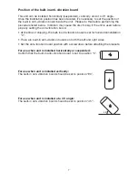
Page 7: ...rd At the time of shipping the built in anti vibration board is set for horizontal installation 0 There are built in anti vibration boards on both the left and right sides Set the anti vibration board...

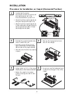
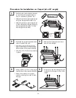
Page 8: ...e hexagonal nuts M6 Pull back the carpet and determine where to attach the unit Stick the supplied double sided tape to the bottom of the brackets B and peel off the paper backing Affix the unit to th...

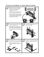
Page 9: ...xagonal nuts M6 Pull back the carpet and determine where to attach the unit Stick the supplied double sided tape to the bottom of the brackets B and peel off the paper backing Affix the unit to the fl...

Page 10: ...s M6 Pull back the carpet and determine where to attach the unit Stick the supplied double sided tape to the bottom of the brackets B and peel off the paper backing Affix the unit to the floor by pres...

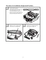
Page 11: ...eft and right sides are set to the horizontal installation position 0 Attach the left and right brackets A using the hexagonal bolt M4 x 5 Determine the mounting location and drill four mounting holes...

Page 12: ...5 Do not expose discs to direct sunlight high humidity or high temperatures for extended periods of time Long exposure to high temperatures can warp the disc 6 Do not stick paper or write anything wit...

Reviews: