D-2000 Series
Revised March 2020
Page | 3-1
SECTION 3: OPERATING INSTRUCTIONS
OPERATING CONTROLS AND INDICATORS
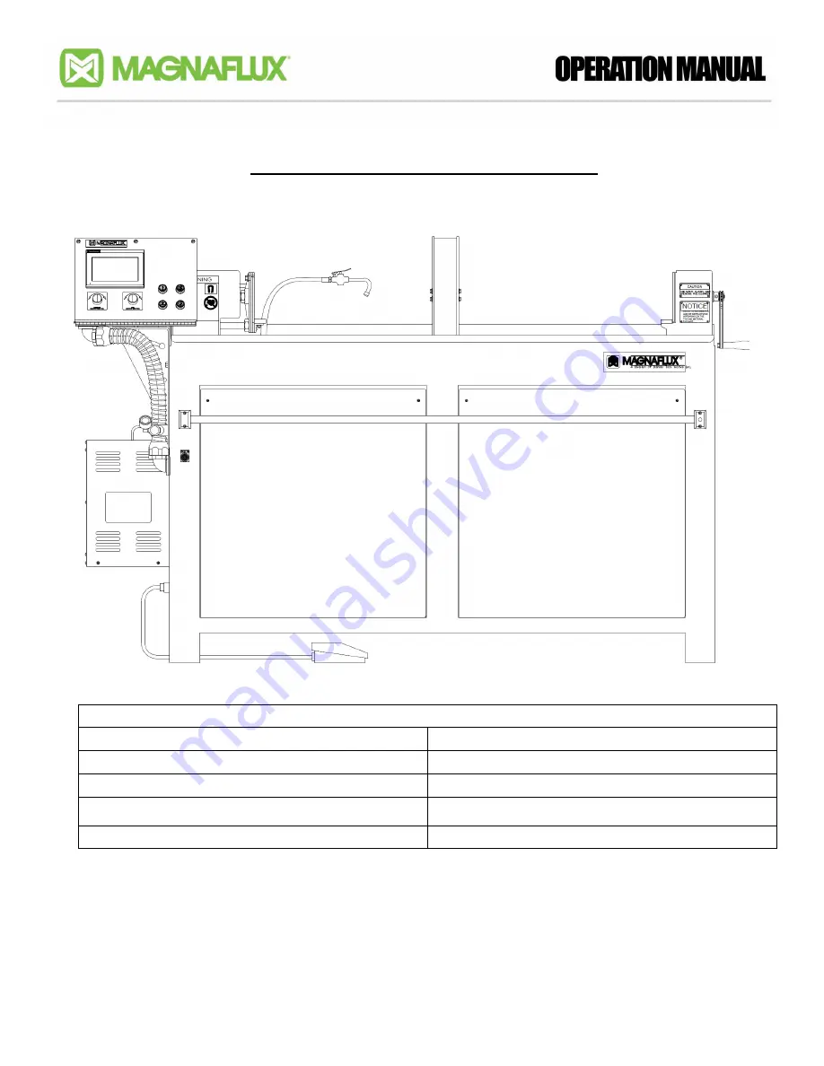
Table 3-1. General Bench Key for Figure 3-1
Item 1: Foot Switch
Item 6: Headstock
Item 2: Power Indicator
Item 7: Spray Nozzle
Item 3: Headstock Pressure Regulator/Gauge
Item 8: Coil
Item 4: Operator Control Cabinet (Figure 3-5)
Item 9: Tailstock
Item 5: Magnetic Current Push-button
Item 10: Push Bar
NOTE:
Adjustment of the pressure regulator for higher or lower pressures will also result in higher or lower
clamping forces. Proper adjustment assures proper clamping force without distorting the test part.
Too low of pressure can cause arcing on the part at high amperage.
Figure 3-1
1
2
3
4
5
6
7
8
9
10
Summary of Contents for D-2000 Series
Page 1: ...D 2000 Series Revised March 2020 Page 1 0 D 2000 SERIES ...
Page 9: ...D 2000 Series Revised March 2020 Page 1 8 PAGE LEFT BLANK INTENTIONALLY ...
Page 20: ...D 2000 Series Revised March 2020 Page 2 11 PAGE LEFT BLANK INTENTIONALLY ...
Page 33: ...D 2000 Series Revised March 2020 Page 3 13 PAGE LEFT BLANK INTENTIONALLY ...
Page 40: ...D 2000 Series Revised March 2020 Page 4 7 PAGE LEFT BLANK INTENTIONALLY ...
Page 45: ...D 2000 Series Revised March 2020 Page 5 5 PAGE LEFT BLANK INTENTIONALLY ...
Page 48: ...D 2000 Series Revised March 2020 Page 6 3 PAGE LEFT BLANK INTENTIONALLY ...


