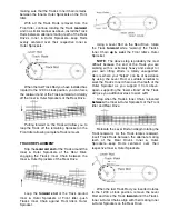
Bar, the #441 Brake Switch should be
open
(the
#440 Leaf Spring would have rotated up and
away); the light of the continuity tester should now
be
off
!
If
both
of the above conditions are not met,
you must adjust the height of the #441 Switch.
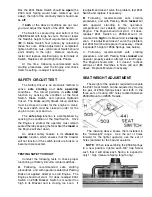
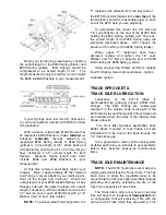
The Switch is secured top and bottom of the
#538 Bracket with large hex nuts. Raise or lower
the Switch’s height to meet requirements (
A
) and
(
B
) in Brake Switch Test (above) by relocating
these hex nuts. When adjustment is completed,
tighten both hex nuts...terminals of Switch should
point directly to the right. Remove continuity
tester and replace electrical plug on terminals of
Switch. Replace Left and Right Side Panels.
At this time, following recommended safe
starting procedures, start the Engine and check
Switch’s setting...readjust if necessary.
SAFETY CIRCUIT TEST
The Safety Circuit is an electronic method to
sense
safe starting
and
safe operating
conditions. The Circuit performs its
safe start
function by sensing the condition of the Seat
Switch, Brake Switch, and optional Hydraulic
Circuit. The Brake and Hydraulic circuit switches
must be closed in order for the engine to crank.
The seat switch must be closed in order for the
engine to turn over and run.
The
safe stop
function is accomplished by
sensing the condition of the Seat Switch. Once
the Engine is started, the operator must remain
seated thereby keeping the Seat Switch
closed
or
the Engine will shut down.
An added safety feature is its
closed to
operate
function which ensures that the Crawler
will not function if the switch leads are broken or
become disconnected.
TESTING SAFETY CIRCUIT
Conduct the following tests to check proper
functioning of Safety Circuit & related switches:
A
. Following recommended safe starting
procedures, and with operator seated but Parking
Brake not applied, attempt to start Engine. The
Engine should not start. If it does, readjust #441
Switch on #538 Bracket; Switch is mounted too
high in its Bracket and is closing too soon. If
readjustment doesn’t solve the problem, test #441
Switch and replace if necessary.
B
. Following recommended safe starting
procedures, and with Parking Brake
locked
but
with operator standing in the operator’s
compartment (not seated), attempt to start the
Engine. The Engine should not start. If it does,
readjust #441 Switch on #503A Mount; it’s
mounted too
high
in its Mount and is
closing
too
soon. If readjustment doesn’t solve the problem,
test #441 Switch and replace if necessary. Check
“expanded” height of #506 Springs (see below).
C. Following recommended safe starting
procedures, and with Parking Brake
locked
and
operator properly seated, attempt to start Engine.
The Engine should start. If it doesn’t, recheck
settings of #441 Switches in Tests (
A
) and (
B
)
above. Replace Module if necessary.
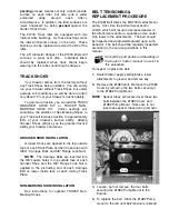
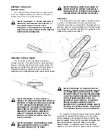
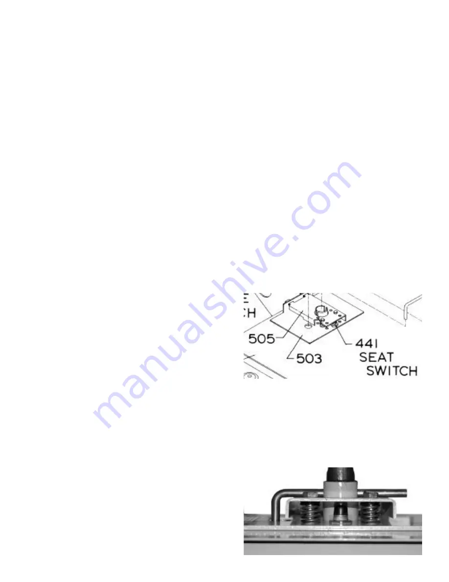
SEAT WEIGHT ADJUSTMENT
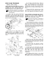
The weight of the operator required to activate
the #441 Seat Switch can be adjusted by moving
the pair of #506 Springs back and forth in the
three sets of mating 3/8” holes located between
#503A Mount and #505 Treadle.
The drawing above shows them installed in
the “mid-weight” range. Use the set of holes
forward for the lighter operator; use the set of
holes rearward for the heavier operator.
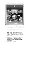
NOTE
: When reassembling the #506 Springs
to a new position, tighten each 3/8” Cap Screw
such that it will allow each Spring to expand to
only 1” high (measure Spring length only).

