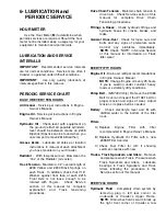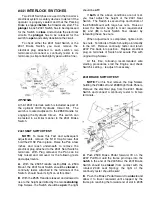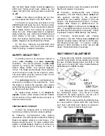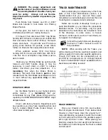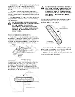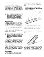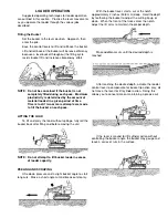
Shims until the #1090 Drive Chain is tight...you
may lightly
tap in
the last shims but do not
drive
them in (that would indicate you are over-
tensioning the Chain).
NOTE
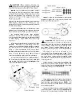
: Add the same number of Shims on
each end of #214 Rear Axle to make sure the
Rear Axle will stay horizontal. Replace Cotter
pins removed above and secure them. Tighten
both 1/2” Cap Screws that secure each #231 Axle
Support. This tightening step will draw the Shim
packs
tight and create the proper slack in the
#537 Drive Chain.
REMEMBER to make this #1090 Drive
Chain Adjustment to both sides of Crawler!
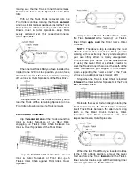
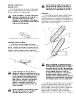
Using original bolts, replace the #1212R &
#1212L Guards and tighten.
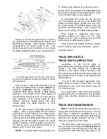
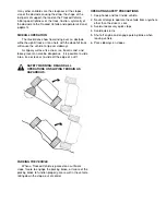
Follow Track Tensioning procedure in this
manual and re-tension both Tracks. Remove
Crawler from blocks and test run. Check Drive
Chain adjustment and readjust if necessary.
PARKING/EMERGENCY BRAKE
The Parking/Emergency Brake provides a
force approximately equal to the strength of the
Crawler’s drive system and is used in a number of
ways. One way, is as a Parking Brake. In this
capacity, it holds the Crawler in position when the
Engine and drive system is shut off.
In addition, it provides a
safe start mode
, as
the Brake must be engaged before starting the
Engine. If the operator inadvertently touches the
Track Drive Controls during Engine starting, the
Brake will severely load the drive system and
potentially kill the Engine (unless the Track Drive
Controls are released immediately).
The Brake’s other use is that of an Emergency
Brake. If you should ever lose Engine or drive
system power, the Brake can be activated
instantly to hold the Crawler safely in position.
DISK BRAKE ADJUSTMENT
CAUTION
: Read the following Disk Brake
and Disk Puck instructions in their entirety
before
attempting
any
Disk
Brake
adjustments!
µ
Consult the part photos and drawings at
the back of tractor manual to assist in
this procedure.
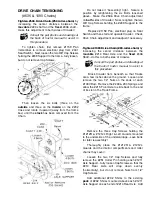
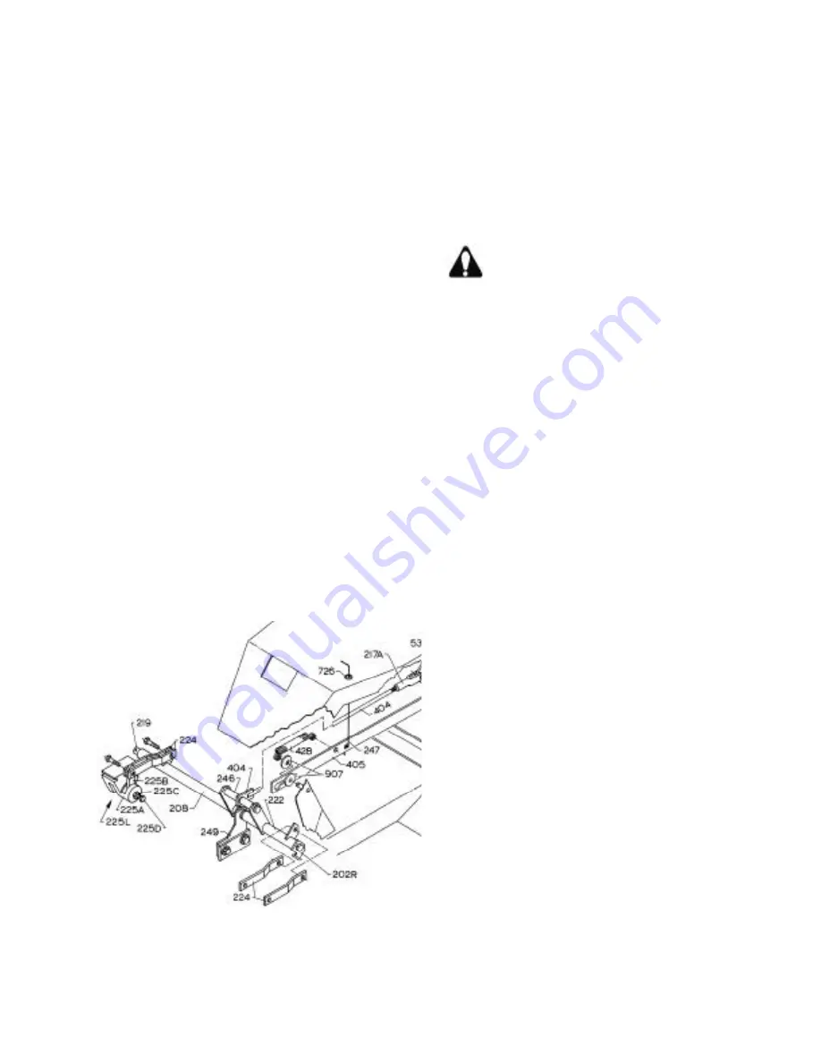
Release Parking Brake. Unscrew a few turns
the #225C Jam Nut on #225R & #225L Right &
Left Disk Brakes to release each Jam Nut’s
respective #225D Threaded Adjuster Pin.
Rotate the Adjuster Pin on each Disk Brake
in
(clockwise when viewing
face
of Brake) until it
stops...don’t overtighten, just tighten to the point
where it stops and the
pucks
(brake linings) are
tight on the Brake Disk.
Now counter-rotate (counter-clockwise) the
Adjuster Pin of each Disk Brake exactly 180
degrees. The pucks should have lost their grip on
their respective Disks and both Brake assemblies
should be free to move.
Push forward on the Parking Brake and watch
as each Disk Brakes’ #225B Lever begins to
rotate forward, and tighten the pucks of each
Brake on their respective Disk. The #246 Evener
Rod is the
central pull device
that connects the
two Disk Brakes together, and it
must be kept
parallel
to the #219 Pivot Rod.
If it is not parallel, determine which of the two
#208C Levers (connecting the #246 Evener) is
further rearward. Release the Brake. Rotate just
a few degrees counter-clockwise, the Adjuster Pin
of the Disk Brake that is closest to the most
rearward #208C Lever. Push forward on Brake
and recheck for parallelism of #246 Evener &
#219 Pivot...readjust if necessary. When
satisfied, hold each #225D Adjuster with wrench
and tighten its respective #225C Jam Nut.

