1-6-2
E9E8ADC
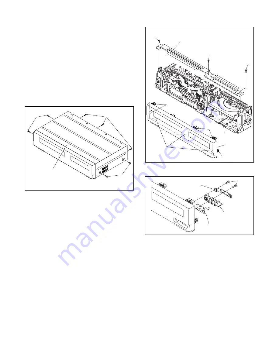
CAUTION 1: Locking Tabs (L-1) and (L-2) are fragile.
Be careful not to break them.
1-1. Release five Locking Tabs (L-1).
1-2. Release three Locking Tabs (L-2)
1-3. Disconnect Connector (CN2609), and remove
the Front Assembly.
2. When reassembling, solder wire jumpers as shown
in Fig. D9.
3. Before installing the Deck Assembly, be sure to
place the pin of LD-SW on Main CBA as shown in
Fig. D9. Then, install the Deck Assembly while
aligning the hole of Cam Gear with the pin of LD-
SW, the shaft of Cam Gear with the hole of LD-SW
as shown in Fig. D9.
(S-1)
(S-1)
(S-1)
[1] Top Cover
Fig. D1
(L-1)
(S-2)
(S-2)
(S-3)
(L-2)
(L-1)
(L-1)
[2] Front
Assembly
[3] Front Bracket
CN2609
Fig. D2
Fig. D3
(S-4)
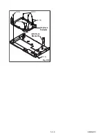
Jack Earth Plate
[4] Jack Bracket
[5] Front
Jack CBA
Summary of Contents for ZV420MW8 - DVDr/ VCR Combo
Page 19: ...1 6 6 E9E8ADC Fig D10 19 Deck Pedestal 20 Front Bracket R S 18 S 18 S 18 S 18 S 19 ...
Page 39: ...1 12 3 Main 1 7 Schematic Diagram E9E8ASCM1 ...
Page 41: ...1 12 5 Main 3 7 Schematic Diagram E9E8ASCM3 ...
Page 42: ...1 12 6 Main 4 7 Schematic Diagram E9E8ASCM4 ...
Page 43: ...1 12 7 Main 5 7 Schematic Diagram E9E8ASCM5 ...
Page 44: ...1 12 8 Main 6 7 Schematic Diagram E9E8ASCM6 ...
Page 45: ...1 12 9 Main 7 7 Schematic Diagram E9E8ASCM7 ...
Page 47: ...1 12 11 Front Jack Schematic Diagram E9E8ASCFJ ...
Page 63: ...1 15 3 R4NTI Push close 0 08 V 0 02 s Push Close detection Threshold level ...


