30
(E)
MG10-P1 / MG10-P2
Details of command operations
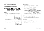
ASCII code is used for all the commands. A command is terminated
by “
CR
” or “
CR
”
+
“
LF
”. (“
CR
”: carriage return; “
LF
”: line feed)
•
Select using communication setting switch No. 2. on main unit.
OFF : “
CR
”
+
“
LF
” (factory setting)
ON : “
CR
”
•
On the pages to follow, “
e
e
e
e
e
” and “
r
r
r
r
r
” are used to indicate the
value to be set.
•
When inputting a setting, a numerical value inside the assigned
range must be selected: otherwise, the value will not be set.
•
If no polarity (
+
or
−
) is input, it is construed as
+
.
[Data which is input ahead of the commands]
Data
Selection range
Symbol used in descriptions
Unit number
0 to F or
∗
q
q
q
q
q
Module number
0 to F or
∗
w
w
w
w
w
•
0 to F are hexadecimal numbers which are equivalent to 0 to 15
in the decimal system.
•
∗
is used when the settings are to be set for all units or all
modules.
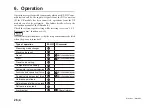
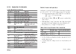
6-1-5. Operation Commands
List of operation commands
Command Setting item
Remarks
R
Load the data of all the channels.
r
Load the data of specific channels.
P-P
Switch to the peak-to-peak value mode.
MAX
Switch to the maximum value mode.
MIN
Switch to the minimum value mode.
REAL
Switch to the current value mode.
MODE
Set the measuring
For details on how to set the
mode.
measuring modes, see
section 5-4.
RCL
Recall the preset value.
RES
Reset.
(Zero reset/reference point setting cancel)
START
Start.
P
Set the preset value.
For details on how to set this
value, see section 5-4.
CH
Set the comparator
For details on how to set
upper limit.
this value, see section 5-4.
CL
Set the comparator
For details on how to set
lower limit.
this value, see section 5-4.
SCN
Set the comparator
For details on how to set this
set number.
number, see section 5-4.
PAU
Set the peak value data update stop.
LCH
Set the current value output data latching.
L
Load the reference point.
Summary of Contents for MG10-P1
Page 3: ...J 1 MG10 P1 MG10 P2...
Page 4: ...2 J MG10 P1 MG10 P2 DC AC...
Page 6: ...MG10 P1 MG10 P2 ii J Microsoft Windows Windows 7 35 8 36 8 1 36 8 2 37 8 3 37 9 38...
Page 9: ...MG10 P1 MG10 P2 J 3 1 3 BCD DG DT DL DK PLC 16 RS 232C...
Page 10: ...MG10 P1 MG10 P2 4 J 2 6 7 4 5 8 2 9 10 11 12 13 14 1 3...
Page 12: ...MG10 P1 MG10 P2 6 J 3 3 1 16 1 2...
Page 13: ...MG10 P1 MG10 P2 J 7 3 4 2 3 1 1 4 3 2 I F I F 1 1...
Page 14: ...MG10 P1 MG10 P2 8 J 2 I F I F 3 1 3...
Page 15: ...MG10 P1 MG10 P2 J 9 2 DIN DIN DIN 3 3 DIN DIN DIN 35 mm 1 DIN...
Page 16: ...MG10 P1 MG10 P2 10 J 3 5 1 3 I O 3 GND 2 Vin DC 12 V 24 V 1 FG 2 3 3 4 1...
Page 17: ...MG10 P1 MG10 P2 J 11 3 6 1 LZ61 CE08 RS 232C I F 3 7 1 RS 232C DZ252 RS 232C...
Page 19: ...MG10 P1 MG10 P2 J 13 4 2 3 DK 1 1 mm 2 1 mm 3...
Page 20: ...MG10 P1 MG10 P2 14 J 4 2 5 P P 4 RS 232C SETUP P CLOSE 1 mm RS 232C 1 4 2 4 0...
Page 21: ...MG10 P1 MG10 P2 J 15 4 2 6 RS 232C MG30 B BCD 4 RS 232 NG U GO G GO G GO G NG L...
Page 22: ...MG10 P1 MG10 P2 16 J ON P P OFF 4 2 7...
Page 24: ...MG10 P1 MG10 P2 18 J 5 2 5 2 1 1 0 F...
Page 28: ...MG10 P1 MG10 P2 22 J 7 ASCII ASCII ASCII OK 8 R...
Page 32: ...MG10 P1 MG10 P2 26 J 6 RS 232C I O I F I F I F 4 2 3 OFF RS 232C I O...
Page 40: ...MG10 P1 MG10 P2 34 J 6 2 3 RS 232C MIN 25 ms MIN 1 ms RS RS MIN 2 ms MAX 2 ms MIN 2 ms...
Page 44: ...MG10 P1 MG10 P2 38 J q 12 V 24 V w RS 232C MG10 MG10 e MG10 9 r MG10 t...
Page 52: ...4 E MG10 P1 MG10 P2 6 7 4 5 8 2 9 10 11 12 13 14 1 3 2 Name and Function of Each Part...
Page 94: ...4 G MG10 P1 MG10 P2 6 7 4 5 8 2 9 10 11 12 13 14 1 3 2 Teilebezeichnungen und Funktionen...


