background image


Gauss-/Teslameter 


FH 52 


BA - Nr.: 1620010102


Page 25 


operation using the 

Enter

 key. The captured vale is then shown in the upper left corner of the 

display  together  with  its  sequential  number.  If  multiple  values  are  stored,  the  list  can  be 
browsed using the arrow keys. A new measured value is always appended to the end of the list. 
The  shown  value  can  be  removed  using  the 

Delete

  key.  If  this  key  is  held  down,  multiple 

values  are  deleted  until  the  key  is  released  again.  After  ten  deleted  values  the  deletion  is 
processed faster. 

3.4


Switching between Battery Power and USB Power 


Important! 

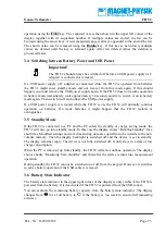
The FH 52 should always be switched off before an USB power supply (AC 
adapter) is connected or removed. 

If a USB power supply  (AC adapter)  is  connected while the  FH 52 is  operated from  batteries 
the  FH 52  might  enter  standby  mode  and  not  recover  from  this  mode  again.  If  this  should 
happen, you must remove the USB power supply again. If the FH 52 does not resume operation 
in battery mode immediately, wait approximately 30 seconds and try to switch it on in battery 
mode again. Then switch it off and connect the USB power supply. 

If  a  USB  power  supply  is  removed  while  the  FH  52  is  on,  the  FH 52  will  normally  continue 
operation  on  batteries.  On  weak  batteries  it  might  happen  that  the  FH 52  restarts  or 
extinguishes. 

3.5


Standby Mode 

If  the  FH 52  is  connected  to  a  PC  and  the  PC  enters  the  standby  or  energy  saving  mode,  the 
FH 52 will also go into standby mode. In this case the display shows “

Entering Standby

” for a 

short time. Modified settings and saved measuring data are copied from the volatile to the non-
volatile  memory.  Then  the  display  backlight  is  switched  off  and  the  device  is  set  to  standby. 
The display remains empty. The device is not fully switched off. It only stays in a state of low 
energy consumption. 

When the PC is wakened up from standby, the FH 52 will also continue operation. The display 
shows  shortly  “

Resuming  from  standby

”  and  thereafter  the  device  returns  into  measurement 

operation. 

During standby the FH 52 cannot be switched on or off from the keypad. However, it switches 
to active battery operation if the USB cable is removed. 

3.6


Battery State Indicator 

The battery state indicator in the upper right corner of the display is only visible if the FH 52 is 
powered from the battery. It is deactivated if the FH 52 is powered from the USB socket. 

You  can  estimate  the  remaining  battery  capacity  from  the  battery  state  indicator.  The  display 
changes  from 

  for  a  full  battery  to 

  if  the  battery  is  too  weak  to  ensure  full  measuring 

accuracy. 

Summary of Contents for FH 52

Page 1: ...BA Nr 1620010102 Emil Hoffmann Strasse 3 50996 Koeln Germany Operating Instructions FH 52 Gauss Teslameter Preserve for future application...

Page 2: ...or disregard of our safety notes If you face any problems while working with the equipment or the operating instructions or if you have any proposals for improvements please do not hesitate to contact...

Page 3: ...anty These contractual warranty provisions are neither extended nor limited by statements in these instructions MAGNET PHYSIK GmbH K ln 1620010102 2016 Passing on and reproduction of these documents a...

Page 4: ...ons to be ordered separately 13 2 8 Taking Into Operation 13 3 Operation 14 3 1 Display 14 3 2 Key Pad 15 3 3 Functions 16 3 3 1 On Off Key Switching the Device On and Off 16 3 3 2 Range Key Range Sel...

Page 5: ...LE 2 AMBIENT CONDITIONS 10 TABLE 3 RANGES 16 List of Illustrations FIG 1 FRONT VIEW OF THE DEVICE 12 FIG 2 DISPLAY DURING MEASUREMENT OPERATION 14 FIG 3 MAIN MENU 18 FIG 4 AC DC MENU 18 FIG 5 UNIT MEN...

Page 6: ...th or considerable material damage may occur if the appropriate safety measures are not taken Warning Means that bodily injury or material damage may occur if the appropriate safety measures are not t...

Page 7: ...limitation can cause danger to life Danger The Hall probe must never be brought into contact with an electrical voltage conductor or close to an electrical high voltage conductor The coating or sleeve...

Page 8: ...repair to ensure that safety features are maintained 1 4 Authorized Operators The FH 52 must only be used by personnel authorized by the owner In this case the owner must place operating instructions...

Page 9: ...any missing parts if not informed within 60 days from date of dispatch Important Check on receipt of goods and before taking the device or accessories into operation whether they show visible signs o...

Page 10: ...USB approx 6 mA from batteries Accessories Options Hall probes Transverse probe or axial probe the probe connection cables are fixed to the probes length 1 5 m 5 ft Hard case Included USB cable USB ty...

Page 11: ...n IEC 61000 4 2 Air discharge 8 kV Contact discharge 4 kV Immunity from electromagnetic HF field amplitude modulation based on IEC 61000 4 3 80 MHz to 1000 MHz 3 V m 80 AM 1 kHz Immunity from electrom...

Page 12: ...ont panel keys and a liquid crystal display LCD Most important user features are only one pushbutton away In Fig 1 the front side of the FH 52 is shown The sockets on the upper side are used for probe...

Page 13: ...s Open the door on the bottom side of the FH 52 Install 4 batteries observing the polarity for each cell into the battery compartment Close the door again 2 Connect the probe Plug the probe into the s...

Page 14: ...e automatically saved when the device is switched off 3 1 Display The figure below shows the measurement display of the FH 52 with all available elements enabled In real operation you will normally us...

Page 15: ...an integrated block of 9 keys and a line arranged above with 3 keys The block contains the following keys On Off Delete Mode Escape Enter and arrow keys in 4 directions The line contains the Range Ze...

Page 16: ...le to the no volatile memory Therefore you should always switch off the device using the On Off key If the device does not contain operational batteries and the USB cable is removed while the device i...

Page 17: ...e Relative function instead of Zero 3 3 4 Reset Key Resetting the Display of Maximum and Minimum Using the Reset key the memories for the maximum and minimum measured values are reset to the current r...

Page 18: ...elected the root mean square RMS value of the field strength or flux density of a periodically alternating magnetic field is displayed If DC is selected the measured value for a static magnetic field...

Page 19: ...iven by the following relation B 0 H 4 10 7 Vs Am H 1 257 10 6 Vs Am H Here 0 is the magnetic field constant or permeability of the vacuum If the unit for the measurement is changed the relative and l...

Page 20: ...f if the signal mode is switched between AC and DC and if the device enters standby The Max Min function can be used together with the relative function The Max Min function is designed to observe slo...

Page 21: ...e is selected Move the cursor using the arrow keys onto the sign or onto the digit to be changed and change them with the arrow keys Terminate editing using Enter or Mode Please note that the RMS valu...

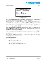
Page 22: ...editing using Enter or Mode If the desired reference value cannot be entered in the active range you can change the range using the Range key without leaving the input line Please note that the automa...

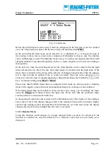
Page 23: ...ally a letter N for north pole and S for south pole can be shown behind the reading N means that the sensor is opposite to a north pole and S means that the sensor faces a south pole see also Fehler S...

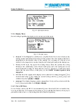
Page 24: ...age path of the probe is checked If no probe is connected or if the voltage path is interrupted open is shown If OK is shown the voltage path is operational For third the probe Current is measured It...

Page 25: ...FH 52 will normally continue operation on batteries On weak batteries it might happen that the FH 52 restarts or extinguishes 3 5 Standby Mode If the FH 52 is connected to a PC and the PC enters the s...

Page 26: ...d the measured values are saved Important You should remove the batteries from the FH 52 if the device will not be used for a longer time This will avoid damage due to leaking batteries 3 7 Probes Two...

Page 27: ...an be damaged Warning Care must be exercised when handling the probe The sensor of the probe is very fragile Stressing the Hall sensor can alter its calibration The probe must not be clamped or presse...

Page 28: ...and falls and the maximum is captured Make note of the probe orientation at the maximum reading to identify the field direction You should consider all the possible contributions to the accuracy of th...

Page 29: ...amed FH 52 Software is available for free download This contains the following components FH 52 Teslameter a simple program for displaying and saving readings and for remote control of the most import...

Page 30: ...de surface of the Hall generator so that an electric voltage the Hall voltage UH can be measured between the opposite sides d B I R UH H The Hall voltage is thus in the first approximation proportiona...

Page 31: ...a year We recommend having this calibration carried out by the manufacturer Magnet Physik or an authorized calibration laboratory 4 4 Troubleshooting Using the Test menu chapter 3 3 16 you can carry...

Page 32: ...entative This probe is not supported is displayed You are trying to use a probe that is not suitable for a FH 52 or the present version of the FH 52 In case of doubt ask Magnet Physik Therefore it is...

Reviews: