DataLogger Series 4 Technical Manual
February 2021
Page 25 of 28
11.2 Version (Firmware) Information
The Version Info screen will display the firmware version. This screen will display for 3 seconds and then
automatically return to the previous Setup menu screen. The user may want to occasionally check if a
new firmware version is available on the columbusmcKinnon.com website under Software Downloads at
https://www.columbusmckinnon.com/en-us/software-downloads/
. Updates are always free and may be
released without notice.
11.3 Diagnostics
The Diagnostics screen presents low-level status information and is mainly for troubleshooting the
DataLogger hardware. The most notable items are the first line which lists a 1 (functional) or 0 (non-
functional) for the Real Time Clock (RTC), Temperature Sensor (TMP), and Accelerometer (ACL). The
currently connected drive, its firmware version, and connection speed are listed on the next three lines.
Other notable items are the consumed space of the internal memory, communication timeouts and the
temperature reading (in Celsius) of the temperature sensor.
11.4 Set Baud
The Set Baud menu allows the user to adjust the Baud Rate for each drive type. Adjusting to a higher
baud rate may increase transfer speeds, depending on the length of the RJ45 cable used. If the cable
exceeds 50 feet, it is possible the DataLogger will not power up. If this is the case, adjust the Baud Rate
to a lower value.
11.5 Test Screen
The hardware components in the DataLogger Series 4 are monitored in real-time, and the function of the
display, LEDs, sensors, flash memory, and keypad keys can be tested in this menu. Upon entering this
menu, the ALM (red), Mode/Service (green), and RUN (green) LEDs will start to blink. This tests if any of
the three LEDs have failed.
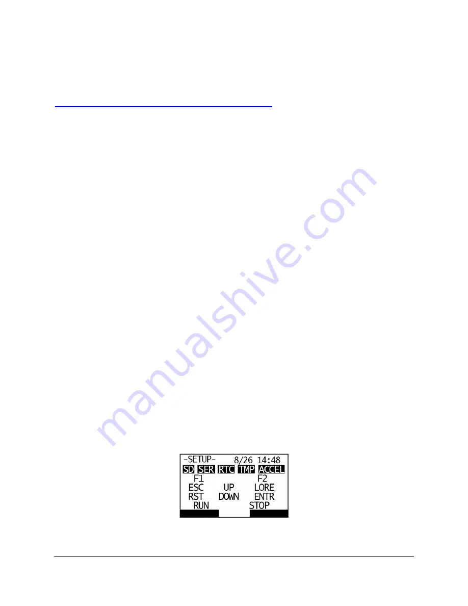
Next, there are five icons on the top row that correspond to internal components including the Internal
Memory (SD), Serial RJ45 connection (SER), Real Time Clock (RTC), Temperature Sensor (TMP), and
Accelerometer (ACCEL). All five of these icons will be shaded as dark boxes if they test out as
functioning properly. If any of these boxes are not dark, it may indicate a failed or malfunctioning
component.
The icons in the lower four rows (F1, ESC, etc.) correspond to their respective keypad keys. Pressing
any individual key will convert its icon to a dark box, which indicates that particular key is functioning
correctly. If the ENTER key is pressed, the entire display will become dark. This is to test if any pixels on
the display have failed. To go back, press the ESC key once. If the ESC key is pressed while on the
Test Screen, its box will turn dark, and the Test Screen will be exited within three seconds.
Figure 13: Test Screen


