STANDARD CONTROL/DISPLAY OPERATION
37
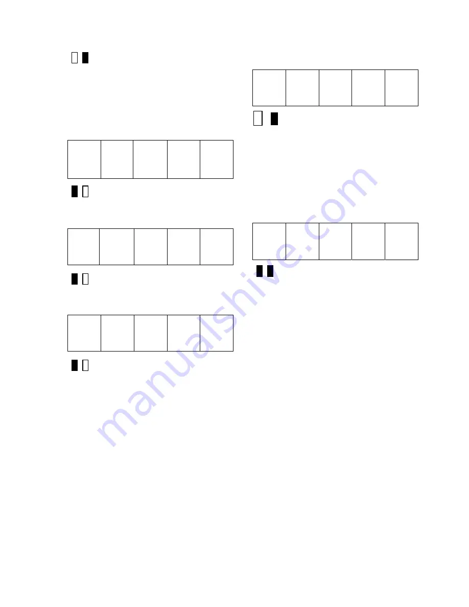
Green LED Lit
3) Use the
▲
and
▼
keys to ramp the
number in the SCDU display to the desired
value. Note that the red LED is lit to indicate
that the value being displayed is NOT the
actual value, but rather is in the process of
being changed. Each parameter has an
upper and lower limit.
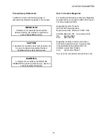
The following display
will occur when the lower limit is exceeded:
__
__
__
__
Red LED Lit
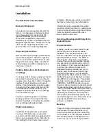
Similarly, if the upper limit is exceeded
, the
SCDU displays:
__
__ __ __
Red LED Lit
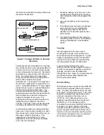
The SCDU display will increment from ‘10.6’
to ‘11.0’ if the
▲
key is pressed 4 times:
1 1.
0
*
Red LED Lit
4) Press the ENTER key to transfer the value
in the SCDU display to the actual value used
by the drive. Note that the green LED will
now light to indicate that this value is now the
actual value for this parameter:
1 1. 0
*
Green LED Lit
If the ENTER key is pressed while the display
is indicating that the upper or lower limit has
been exceeded, the display will change to the
appropriate limit and the green LED will light.
5) Press the DATA/FCTN key to put the
SCDU back into the "Function" level. As with
the example above, the SCDU display will be
similar to:
4 0
Both LED’s Off
All changes made become active values upon
pressing the ENTER key. They remain active
until the next reset, or until the drive is
powered down. When the drive is reset or
powered up the value reverts to the value
stored in NVRAM. If changes are to be
permanent, use function 994 to save the
changed value in NVRAM.
Due to programming considerations it may be
possible to access a value that cannot be
changed. In this case the CDU function will
proceed as described until the ENTER key is
pressed to change the value. In this case the
value will simply ignore any requested
changes and remain the same.
Viewing Monitor Functions
Items that would typically fall into this category
are Speed Feedback, Armature Current and
Armature Voltage.
To view one of these values, it must have
been previously programmed in the the drive.
The following steps show how to display a
given value on the SCDU display.
Summary of Contents for DSD 412
Page 1: ...DSD 412 DC Elevator Drive Technical Manual CS00407 rev 06...
Page 6: ...6...
Page 102: ...MAINTENANCE 102 Figure 24 Connector and E prom Locations...
Page 103: ...MAINTENANCE 103 Figure 25 Test Point Locations...
Page 115: ...OUTLINE DRAWING 100A 115 Figure 26 Drive Chassis Outline DSD 412 100 Amp...
Page 116: ...OUTLINE DRAWING 190A 116 Figure 27 Drive Chassis Outline DSD 412 195 Amp...
Page 117: ...OUTLINE DRAWING 300A 117 Figure 28 Drive Chasis Outline DSD 412 300 Amp...
Page 118: ...LAYOUT DRAWING 100A 118 Figure 29 Layout DSD 412 100 Amp A3 A1 A2 A2 L1 NEG GND L2 L3 POS...
Page 119: ...LAYOUT DRAWING 195A 119 Figure 30 Layout DSD 412 195 Amp A3 A1 A2 A2...
Page 120: ...LAYOUT DRAWING 300A 120 Figure 31 Layout DSD 412 300 Amp A3 A1 A2 A2...
Page 121: ......


