background image


Flex 6EX System Instruction Manual 

March 2016 

Page 32 of 38 


7. OPERATING PROCEDURE 


7.1 TRANSMITTER OPERATION 

7.1.1 General Operating Procedure   

a. 

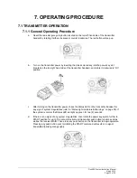
Reset the red emergency stop button located on the top left hand side of the transmitter 
handset by rotating it either clockwise or counter clockwise. The red button will pop up.   


b. 

Turn on the transmitter power by inserting the black-colored key into the power key slot 
(located on the top right hand side of the transmitter handset), and rotate it clockwise to “On” 
position. 


c. 

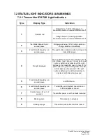
After turning on the transmitter power, check the Status LED on the transmitter handset for 
any sign of system irregularities (refer to “Status Light Indicators & Warnings” on page 35). If 
the system is normal the Status LED will light up green for two (2) seconds. 
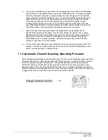
 

d. 

If there are no signs of any system irregularities, then rotate the power key-switch further to 
START position for up to 1.0 second to activate all transmitter push button functions and as 
well as the receiver MAIN. Then press any push button on the transmitter to begin operation. 
Pressing any push button prior to initiating the START command will result in no signal 
transmitted (blinking orange light). 


Summary of Contents for FLEX-6EX

Page 1: ...Flex 6EX System Radio Control Equipment Instruction Manual 0 FLEX 6EX ME R3 March 2016 Copyright 2016 Magnetek Material Handling ...

Page 2: ...lls WI 53051 Telephone 1 800 288 8178 Website www magnetek com e mail mhcustomerservice magnetek com Fax Numbers Main 1 800 298 3503 Sales 1 262 783 3510 Service 1 262 783 3508 Magnetek Inc has additional satellite locations for Canada and the United States For more information please visit http www magnetek com 2016 MAGNETEK All rights reserved This notice applies to all copyrighted materials inc...

Page 3: ...the equipment where the radio system is used Plant safety rules and procedures of the employers and the owners of facilities where the Magnetek Products are being used Regulations issued by the Occupational Health and Safety Administration OSHA Applicable local state or federal codes ordinances standards and requirements or Safety standards and practices for the industries in which Magnetek Produc...

Page 4: ...tings 15 4 1 2 Channel Change via Push Buttons 16 4 1 3 Optional 4 Digit Security Code 17 4 1 4 I CHIP 18 4 2 RECEIVER UNIT 19 4 2 1 System Channel Settings 19 4 2 2 Output Relay Configurations 20 4 2 2 1 Output Relay Types 20 4 2 2 2 Output Relay Actions at 2nd Speed 20 4 2 2 3 START AUX Function 21 4 2 2 4 Momentary Contact 21 4 2 2 5 Toggled Contact 21 4 2 2 6 Auxiliary STOP Push Button Functio...

Page 5: ...7 2 1 Transmitter STATUS Light Indication 35 7 2 2 Receiver STATUS Light Indication 36 7 2 3 Receiver SQ Light Indication 36 7 2 4 Receiver POWER Light Indication 36 7 2 5 Receiver COM Light Indication 36 7 3 TROUBLE SHOOTING TIPS 37 8 SYSTEM SPECIFICATIONS 38 ...

Page 6: ...eiver channels Over one million unique ID codes 20bit Each and every Flex system has its own unique ID codes and serial number never repeats Advanced controls The Flex system utilizes advanced microprocessor controls with 32bit CRC and Hamming Code which provide ultra fast safe precise and error free encoding and decoding Unique I CHIP design The I CHIP functions in a way that is very similar to S...

Page 7: ...ting or maintenance procedure practice etc which if not strictly observed could result in damage to or destruction of equipment or loss of functional effectiveness Cautions are high lighted as shown below CAUTION WARNINGS and CAUTIONS SHOULD NEVER BE DISREGARDED The safety rules in this section are not intended to replace any rules or regulations of any applicable local state or fed eral governing...

Page 8: ...ITS ASSOCIATED EQUIPMENT FAILURE TO FOLLOW THESE WARNINGS COULD RESULT IN SERIOUS INJURY OR DEATH AND DAMAGE TO EQUIPMENT 2 2 GENERAL Radio controlled equipment operates in several directions Quite frequently the equipment is operated in areas where people are working in close proximity to the equipment The operator must exercise extreme caution at all times Workers must constantly be alert to avo...

Page 9: ...nt that utilizes the radio control know how to keep the operator and other people clear of hazardous areas know and follow the local lockout and tagout procedures when servicing radio controlled equipment know and follow all applicable operating and maintenance manuals safety procedures regulatory requirements and industry standards and codes The operator shall not operate the equipment if the dir...

Page 10: ... BATTERIES TO EXPLODE OR DO OTHER SERIOUS DAMAGE FAILURE TO FOLLOW THIS WARNING COULD RESULT IN SERIOUS INJURY OR DEATH AND DAMAGE TO EQUIPMENT Use only batteries approved by Magnetek for the specific product Do not dispose of a battery pack in fire it may explode Do not attempt to open the battery pack Do not short circuit the battery Keep the battery pack environment cool during storage i e not ...

Page 11: ... COULD RESULT IN SERIOUS INJURY OR DEATH OR DAMAGE TO EQUIPMENT Cranes hoists lifting devices and other material handling equipment can be large and operate at high speeds The operator should continuously watch and monitor status of lifted loads know and follow cable and hook inspection procedures The operator shall not lift or move more than the rated load use the crane hoist or lifting device to...

Page 12: ...R HANDSET 3 1 1 External Illustration Fig 01 Fig 02 1 Emergency Stop Button 8 Push Button 5 2 Removable Power Key Switch 9 Strap Ring 3 Push Button 2 10 System Information 4 Push Button 4 11 System Channel 5 Push Button 6 12 Crane Number 6 Push Button 1 13 Battery Cover 7 Push Button 3 14 FCC Information ...

Page 13: ... 2016 Page 12 of 38 3 1 2 Internal Illustration Fig 03 Fig 04 1 Encoder Board 6 I CHIP 2 Aerial Antenna 7 Function Dip Switch 3 Transmitting Module 8 Channel Dip Switch 4 Status LED Display 9 Battery Contact Mechanism 5 Function LED Displays ...

Page 14: ...Manual March 2016 Page 13 of 38 3 2 RECEIVER UNIT 3 2 1 External Illustration Fig 05 1 External Antenna Jack optional 4 SQ LED Display 2 Power LED Display 5 COM LED Display 3 Status LED Display 6 Output Contact Diagram 7 Cord Grip ...

Page 15: ...Flex 6EX System Instruction Manual March 2016 Page 14 of 38 3 2 2 Internal Illustration Fig 06 1 Receiving Module 3 AC Line Filter Relay Board 2 Decoder Relay Board 4 Power Transformer ...

Page 16: ...ns are used for channel programming refer to Fig 08 below The system channels table located on page 27 illustrates which dip switch setting corresponds to which channel Once the transmitter channel is altered make sure to change the receiver channel as well The channel on both the transmitter and the receiver must be identical in order for the system to work To change the receiver channel please r...

Page 17: ... 06 b Select a new channel by pressing PB1 and PB2 on the transmitter Press PB1 to increment the units 1 and PB2 to increment the tens 10 Examples Press PB2 two times and then PB1 four times will give you channel 24 Press PB1 nine times with give you channel 09 c When finished the newly selected channel will appear on the Status LED via series of green and red blinks again d Exit the channel progr...

Page 18: ...t this time fast orange blinks are displayed on the Status LED telling you to reconfirm the 4 digit security code you have just entered A green light will appear once you have re entered the same 4 digit security code again programming completed If any mistake is made during this process or if a red light is shown on the Status LED after you have re entered the security code incorrect input or eve...

Page 19: ...rate according to the channel and push button configurations set on these two dip switches not the ones stored inside the I CHIP Every time when the settings on these two dip switches have changed the new settings will be stored into the I CHIP automatically In this case the previous channel and push button configurations stored inside the I CHIP will be replaced by the new settings For safety pur...

Page 20: ...ated on the receiver module refer to Fig 10 above Only the first six 6 positions are used for channel programming refer to Fig 11 below The system channels table located on page 27 illustrates which dip switch setting corresponds to which channel Once the receiver channel is altered make sure to change the transmitter channel as well The channel on both the transmitter and receiver must be identic...

Page 21: ...2nd speed F R2 shared the same output relay b Four 4 output relays per motion separate 1st and 2nd speed output relays Output relays with Forward 1st speed F1 Reverse 1st speed R1 Forward 2nd speed F2 and Reverse 2nd speed R2 Forward and Reverse 2nd speed with separate output relays 4 2 2 2 Output Relay Actions at 2nd Speed a 3 output relays configuration with Closed Closed contact at 2nd speed At...

Page 22: ...nction with momentary contact For auxiliary applications such as horns or buzzers please connect it to the FUNC output relay wire 5 located inside the receiver unit 4 2 2 4 Momentary Contact When the push button is released the output relay that corresponds to that push button will open refer to page 24 on how to set to this function This type of contact is usually applied to external application ...

Page 23: ...o deactivated when this auxiliary stop push button is pressed refer to page 24 on how to set to this function 4 2 3 Receiver Auto Scanning Settings Receiver Channel Dip switch 1 Scans all 62 channels manufacture preset For standard operation 2 Single fixed channel Auto scanning function disabled 3 Scanning 2 channels only 4 Scanning 3 channels only If the first 6 dip switch positions on the receiv...

Page 24: ...ons refer to Fig 12 13 below Only the first seven 7 dip switch positions are used counting from left to right the 8th dip switch position far right is not used Fig 12 Fig 13 Manufacture preset Dip Settings Function Descriptions of Relays Used 0000000 Normal single speed only F2 R2 relays not used 2 0000001 Closed Closed Relay Action at 2nd Speed separate 2nd speed relay 4 0000010 Closed Closed Rel...

Page 25: ...ting 2 4 left button 5 7 right button Function Description A 1 000 Normal momentary contact B 1 001 Toggled latching contact C 1 011 Normal Start function For added safety you must first rotate and hold the power key switch at START position and then press the intended push button at the same time to activate the output relay D 1 111 Auxiliary Stop Example 1 Left button set to function code A righ...

Page 26: ...itiated JP1 Inserted JP2 Blank Receiver MAIN opens after 5 minutes of system inactivity JP1 Blank JP2 Inserted Receiver MAIN opens after 30 minutes of system inactivity JP1 Inserted JP2 Inserted Receiver MAIN opens after 60 minutes of system inactivity JP3 Blank Press any push button on the transmitter to activate the receiver MAIN at system startup after e stop reset and after system inactivity r...

Page 27: ...completed At this time the I CHIP should also possess the same serial number ID code as the receiver If the Status LED on the decoder module displays a constant red light after inserting the I CHIP programming failed then you must reinsert the I CHIP one more time On the other hand if you wish to transfer system information from I CHIP to receiver then you must first insert JP6 jumper prior to ins...

Page 28: ... 434 075MHZ 101100 13 433 300MHZ 001101 45 434 100MHZ 101101 14 433 325MHZ 001110 46 434 125MHZ 101110 15 433 350MHZ 001111 47 434 150MHZ 101111 16 433 375MHZ 010000 48 434 175MHZ 110000 17 433 400MHZ 010001 49 434 200MHZ 110001 18 433 425MHZ 010010 50 434 225MHZ 110010 19 433 450MHZ 010011 51 434 250MHZ 110011 20 433 475MHZ 010100 52 434 275MHZ 110100 21 433 500MHZ 010101 53 434 300MHZ 110101 22 ...

Page 29: ... separate 2nd speed configurations please refer to page 20 For 4 relay closed closed and 4 relay opened closed relay configurations please refer to page 20 For 12 24VDC power supply wire 1 corresponds to the negative charge and wire 3 corresponds to the positive charge Wire 2 is for GROUND Wire 6 is for Normal Close and wire 8 is for Normal Open MAIN output ...

Page 30: ...hannels 2 Make sure the receiver is not set to the same channel as any other systems in use in the surrounding area 3 Make sure that the crane or equipment is working properly prior to installation 4 Make sure the power source to the receiver is set correctly 5 Switch off the main power source to the crane or equipment prior to installation 6 3 STEP BY STEP INSTALLATION Fig 16 ...

Page 31: ... accommodate the receiver refer to Fig 16 on page 29 If an external antenna is used always locate the receiver where the antenna is free from any obstacles from all directions to avoid the possibility of antenna damage 4 When installing an external antenna you must connect the SMA jack located inside the receiver and make sure to set the jumper to EXT position refer to diagram below 5 For better r...

Page 32: ...rly opens and closes the mainline disconnect contactor 2 Test the operation of each function to ensure it corresponds to the transmitter direction labels or the pendant it is replacing 3 Test the limit switches if any to see if they are working properly 4 If your new remote control is replacing an existing pendant make sure it is completely disconnected and placed in a safe location to prevent unw...

Page 33: ...it clockwise to On position c After turning on the transmitter power check the Status LED on the transmitter handset for any sign of system irregularities refer to Status Light Indicators Warnings on page 35 If the system is normal the Status LED will light up green for two 2 seconds d If there are no signs of any system irregularities then rotate the power key switch further to START position for...

Page 34: ...so be disconnected temporarily when the receiver encounters strong radio interference or when the operator is controlling the crane or equipment beyond the transmitting range To resume operation just rotate the power key switch to START position to reconnect the receiver MAIN g To turn off the transmitter power just rotate the power key counter clockwise to the Off position it will disconnect the ...

Page 35: ...unscrewing the battery cover located on the backside of the transmitter refer to Fig 17 below During battery installation make sure that the blue ribbon is centered between the two batteries After changing the batteries also make sure that all screws are tightened to avoid water moisture dirt grease or other liquid penetration Fig 17 ...

Page 36: ...g on the transmitter power 4 No light displayed When a defective push button condition occurs 2 red blinks type 3 above find out which push button is defective by pressing all the push buttons on the transmitter one at a time If the push button is in good working order the LED will not light up when pressed If the push button is defective the LED will continue to display 2 red blinks when pressed ...

Page 37: ...Receiver under voltage LV output relay activated 6 No light displayed Decoding microprocessor is defective 7 2 3 Receiver SQ Light Indication Type Display Type Red Indication 1 Fast blinks Transmission received 2 Completely off No transmission 3 Blinks intermittently Other radio interference 7 2 4 Receiver POWER Light Indication Type Display Type Red Indication 1 On Power to receiver 2 Off No powe...

Page 38: ... startup procedure is initiated within 100 meters 300 feet from the receiver location No response when transmitter push button is pressed Damaged hardware Defective transmitting and receiving module Check the SQ display on the face of the receiver unit If it does not light up when push button is pressed then either the transmitting or receiving module is defective First replace the transmitting mo...

Page 39: ...iver Sensitivity 116dBm Antenna Impedance 50 ohms Responding Time 60 Milliseconds average Transmitting Power 0 3mW Enclosure Type NEMA 4X Enclosure Rating IP 66 Output Contact Rating 250V 8 Amps Transmitter Operating Voltage DC 3 0V Receiver Power Consumption 11 0 VA Receiver Supply Voltage Voltage Setting Min Max 24VAC 22 26VAC 42VAC 38 46VAC 48VAC 43 53VAC 110VAC 104 126VAC 220VAC 207 253VAC 380...

Reviews: