background image


Magneti Marelli Aftermarket Spółka z.o.o. 

Plac Pod Lipami 5, 40-476 Katowice 

Tel.: + 48 (032) 6036107, Faks: + 48 (032) 603-61-08 

e-mail

checkstar@magnetimarelli.com 

www.magnetimarelli-checkstar.pl 

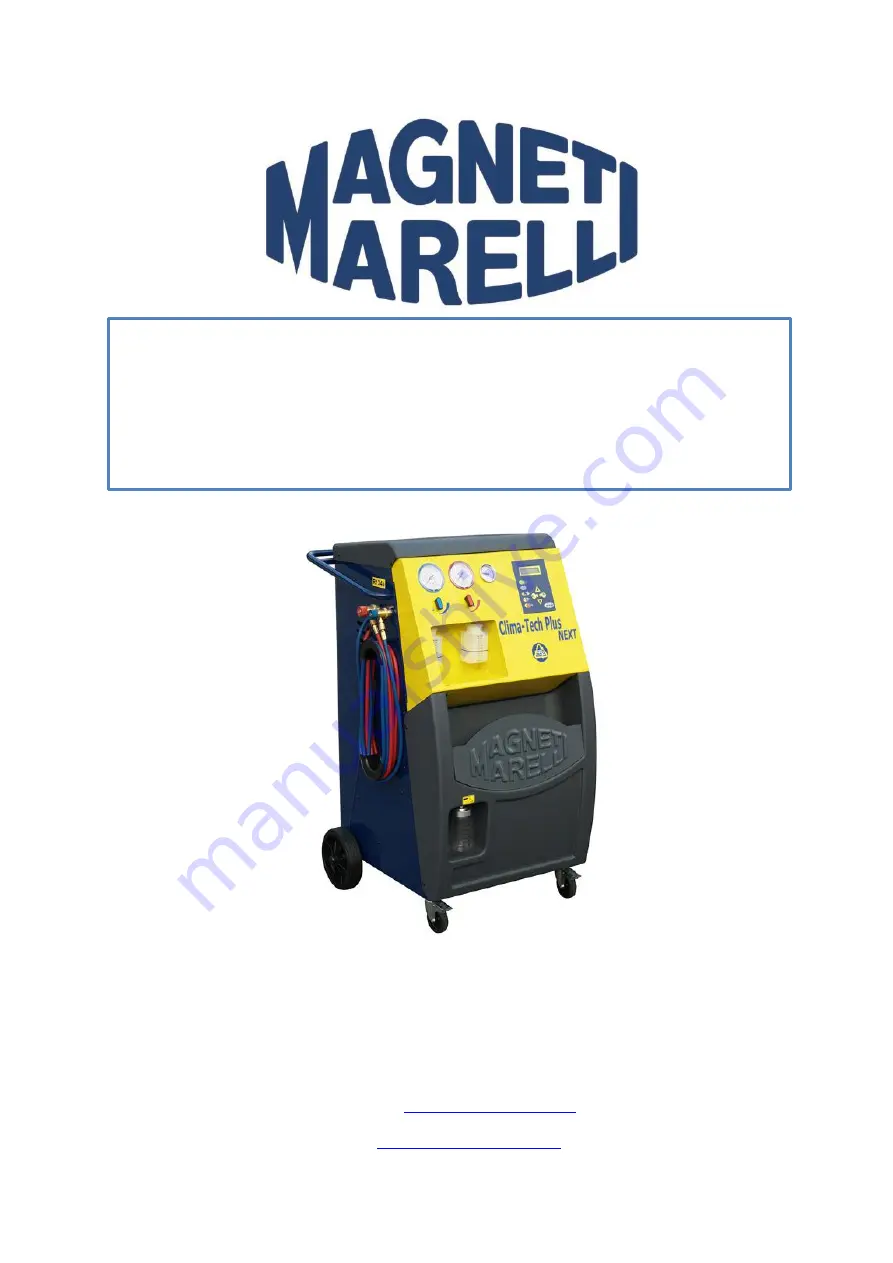
Clima-Tech   Plus / Hd Evolution 

User’s Manual 

007950015110


Summary of Contents for Clima-Tech Plus

Page 1: ...ermarket Sp ka z o o Plac Pod Lipami 5 40 476 Katowice Tel 48 032 6036107 Faks 48 032 603 61 08 e mail checkstar magnetimarelli com www magnetimarelli checkstar pl Clima Tech Plus Hd Evolution User s...

Page 2: ...herefore the only task of the user is to use and maintain the device correctly according to the indications in this manual That is why it is important to stress at the beginning that Before any use of...

Page 3: ...a shipment of the device to the Magneti Marelli Technical Service on reporting the failure The device must be shipped in appropriate packaging that protects it against possible damage in transport Mag...

Page 4: ...LIMA TECH TOP in a completely safe way and with maximum efficiency exceptional in other similar equipment The device was not designed for disposal see Glossary section 3 2 Description and layout of co...

Page 5: ...5 FILTER 16 COMPRESSOR 17 VACUUM PUMP 18 WEIGHT 60 kg 19 OIL INJECTION RESERVOIR 20 USED OIL RESERVOIR 21 UV CONTRAST RESERVOIR 22 EXPANSION VALVE 25 RUBBER HOSE 26 RUBBER HOSE 27 CONDENSER FAN 28 HP...

Page 6: ...u S LED Power supply STOP BACK LED F A LED Recycling phase indication B LED Emptying phase indication C LED Oil injection indication D LED UV additive injection indication E LED Installation charging...

Page 7: ...Final vacuum 5 Pa 0 05 mbar Filtration unit 2 filters in series DIMENSIONS 1222x629x628 mm Weight 90 kg Weight HD version 105 kg 3 3 2 Energy consumption Supply voltage 230 V 50 60 Hz Power 770 W 3 3...

Page 8: ...rant may result in bodily damage and even loosing one s sight Avoid skin contact as low boiling point approx 30oC may cause frostbite Avoid inhaling refrigerant vapors Before connecting the unit to th...

Page 9: ...ocessing Recycling removal of contamination present in the refrigerant by separation of oil and non condensing substances and single or multiple filtration through a special device which reduces humid...

Page 10: ...aminated the refrigerant is it may be checked using a special acidity and water content measurement set 4 2 4 Recycling remarks Replace the recycling system filter set regularly see Messages section t...

Page 11: ...mperature between 5 C and 40 C humidity of up to 50 at 40 C The device shall be operated in a place with sufficient lighting average workshop lighting value shall be 500 750 1000 lx Do not operate the...

Page 12: ...esigned in such a way that the heaviest components are located in its bottom part which assures low center of gravity Nevertheless there is a risk that inclined device may fall down 5 3 Preparation fo...

Page 13: ...shows the installed software version date and time for a couple of seconds CLIMA TECH EVO SW xx xx xx xx Then the display shows available resources stand by Refrigerant g xxx 5 5 Switching off To stop...

Page 14: ...ing tanks without suction pipe have only one valve and therefore must be put with their top down to let the liquid refrigerant flow TANKS Tank with a float Tank without a float Open HP valve on the ma...

Page 15: ...d Confirm by pressing ENTER Close cylinder valve Follow the on screen instructions Confirm by pressing ENTER Wait Refrigerant recovery from tubes Process finished Confirm by pressing ENTER The maximum...

Page 16: ...k The valve is automatically energized by the system each time there is non liquefied gas in the tank and their pressure is greater than the calibration pressure The purpose of the non liquefied gasse...

Page 17: ...tects a pressure growth in the system during vacuum leak test Repair the A C system Select ENTER to continue Select STOP RETURN to return to standby mode Insufficient vacuum Continue mB XXX This messa...

Page 18: ...e if the target refrigerant quantity was not filled despite the maximum duration if HP LP A C system is selected The remaining refrigerant will be sucked in to the system by the compressor Follow the...

Page 19: ...sage appears one year after database memory card activation Select ENTER Please contact the distributor Select ENTER to go to standby mode See Replacing memory card Replacing the memory card into a ca...

Page 20: ...instructions on the display 7 1 1 Memory card functions optional For installed memory card in the automatic program specific car model may be selected from the database Moreover a diagnosis mode is av...

Page 21: ...1 2 3 4 5 6 7 8 9 Space A B C D E F G H I J K L 0 M N O P Q R S T U V W X Y Z a b z c y x w v u t s r q p o n m l k j i h g f e d UP DOWN...

Page 22: ...TRY AGAIN and confirm by pressing ENTER to start servicing according to previous maintenance parameters select PREVIOUS SERVICE DATA and confirm by pressing ENTER to display the last vehicle filling p...

Page 23: ...nfirm by pressing ENTER Specify refrigerant weight User vehicles Select using UP DOWN buttons Confirm by pressing ENTER Specify refrigerant weight Refrig g XXXX Specify the correct refrigerant weight...

Page 24: ...tered data press and hold ENTER button for 3 seconds while previous overhaul parameters are displayed To add a new user vehicle select one of the empty slots in the model list and confirm by pressing...

Page 25: ...t using UP DOWN buttons Confirm by pressing ENTER Specify refrigerant weight Refrig g XXXX Specify the correct refrigerant weight using UP DOWN buttons Confirm by pressing ENTER Refrigerant qty g XXXX...

Page 26: ...See 9 2 1 User vehicles 8 4 User program When entering the program selection mode see 9 PROGRAMS the following menu appears Auto Progr User progr Select using UP DOWN buttons Confirm by pressing ENTE...

Page 27: ...s displayed Manual Oil UV Synchro Oil Uv Select using UP DOWN buttons Confirm by pressing ENTER If synchronized oil UV feeding option is selected the station will suggest switching into Synchronic oil...

Page 28: ...is selected the following message is displayed Contrast qty to be introd g 10 Use UP DOWN buttons to select contrast quantity to be introduced Confirm by pressing ENTER The station will suggest going...

Page 29: ...he system was emptied System leak test is then started Min pressure growth control Oil recovery in process The station will remove used oil to the used oil tank 21 Please wait Recycling finished g XXX...

Page 30: ...vice automatically switches to the next phase 9 3 2 Manual oil UV injection Oil feeding Check if the quality of oil in the tank is sufficient Press Enter to confirm switching into oil injection phase...

Page 31: ...a odwo ania Diagnostics NB It is suggested that a diagnosis of the installation is performed even without the expansion card Close HP and LP valves Start the motor and keep the rotational speed at 1...

Page 32: ...system Disconnect the device from the vehicle A C system Open LP and HP valves Confirm with Enter Warning Refrigerant recovery from tubes This message confirms refrigerant recovery from tubes Close LP...

Page 33: ...ilures The diagnostics option is available after completing the filling phase or by selecting the appropriate menu option Close LP and HP valves Follow the instructions Press Enter to confirm The mess...

Page 34: ...g tubes Disconnect HP LP tubes from the system Disconnect the device from the system and confirm with Enter Open LP HP valves Follow the instructions Confirm with ENTER Wait Recovery of refrigerant fr...

Page 35: ...be from the system Follow the instructions Confirm with ENTER Wait Refrigerant is recovered from the tubes The device recovers the refrigerant still present in the tubes The display will show Close LP...

Page 36: ...Personalizing report data Select User s data to modify printout header The header may contain 5 to 20 characters Repeat printing User s data Use Up and Down buttons to select the desired option Confir...

Page 37: ...05 Confirm with ENTER Refrigerant counter Vacuum pump counter Use Up and Down buttons to select the counter to reset Confirm with ENTER If refrigerant counter is selected the display will show the fol...

Page 38: ...nfirm with ENTER Save data User models Confirm with ENTER Transfer from mainboard to memory card Use Up and Down buttons to select the desired menu Confirm with ENTER Save data Confirm with ENTER Savi...

Page 39: ...tivities are limited to a minimum and their frequency is very low each activity performed periodically is monitored by counters Once a counter has reached the maximum display will show the following m...

Page 40: ...ols 1 Phillips screwdriver 2 socket wrenches 12 mm 1 Disconnect the station from the power mains 2 Unscrew 4 screws fixing the bottom panel to the station body and remove the panel 3 Put a tray under...

Page 41: ...f the stations which are not specifically referred to in this section Required tools 1 Phillips screwdriver 2 socket wrenches 12 mm 19mm 1 Disconnect the station from the power mains 2 Unscrew 4 screw...

Page 42: ...ceed as follows It is forbidden to perform activities on the device components which are not specifically referred to in this section Required tools 1 Phillips screwdriver 1 Disconnect the device from...

Page 43: ...ical and electronic equipment manufacturers arrange for appropriate systems for collection of these devices for disposal At the end of life of your product contact your distributor to obtain informati...

Page 44: ...DIAGRAM Magneti Marelli Aftermarket Sp ka z o o Plac Pod Lipami 5 40 476 Katowice Tel 48 032 6036107 Faks 48 032 603 61 08 e mail checkstar magnetimarelli com www magnetimarelli checkstar pl...

Reviews: