background image

Barrier MHTM

TM

 MicroDrive Access and Parking 


Assembly and installation 


76 


5815,5013US / Version 05 


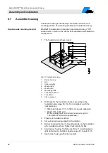
Fig. 34:  Balancing springs in the lever system. 

Barrier arm 

Balancing spring 

Screw with locknuts  


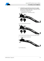
8.14.1  Setting balancing springs 

Check and adjust balancing 

springs 

Check balancing springs with the motor warm from operation. 
1. 

Secure barrier danger area e.g. with barrier tape. 


WARNING! 
Danger of crushing between barrier arm and barrier housing! 

2.  Switch off power supply. Ensure that the system is powered 

down. Secure against reactivation.  


3.  Place barrier arm in the 30° position manually. If required, 

push straight through the upper tool bore with a tool to press 

the lever arm from the dead point.  

 See page 119, chapter 12.5. 

4.  Let go of barrier arm. 


If the barrier arm stays in the 30° position, the balancing 

springs are set correctly. 


If the barrier arm does not stay in the 30° position, the 

balancing springs must be adjusted. 

Summary of Contents for MHTM MicroDrive Access Series

Page 1: ...Operating Instructions Barrier MHTMTM MicroDrive Access and Parking Doc ID 5815 5013US Version 05...

Page 2: ...2 5815 5013US Version 05 MAGNETIC Automation Corporation 3160 Murrell Road Rockledge Florida 32955 USA Tel 1 321 635 8585 Fax 1 321 635 9449 E Mail info ac magnetic com Internet www ac magnetic com...

Page 3: ...e moving barrier arm in sight until it is completely closed or opened No one should cross the path of a moving barrier arm Test the barrier system monthly After adjusting the force or the limit of tra...

Page 4: ...Barrier MHTM TM MicroDrive Access and Parking 4 5815 5013US Version 05...

Page 5: ...2 3 Changes and modifications 16 2 4 Specialists and operating personnel 17 2 4 1 Requirements 17 2 5 Personal protective equipment 18 2 6 Occupational safety and special dangers 18 2 6 1 Danger symb...

Page 6: ...8 Assembly and installation 48 8 1 Safety 48 8 2 Required steps 50 8 3 Foundation and empty conduits 51 8 3 1 Foundation and empty conduits for the barrier 52 8 3 2 Foundation and empty conduits for...

Page 7: ...ctive devices 86 9 3 Connecting the mains supply 86 9 4 Connect customer s control lines signalling devices 88 9 4 1 Connecting safety devices 89 9 4 2 Plausibility check of the safety devices 90 9 4...

Page 8: ...ing and error messages Motor GW 114 12 3 3 Event warning and error messages Detector 117 12 3 4 Event warning and error messages All modules 117 12 4 Reset the barrier 118 12 5 Closing or opening the...

Page 9: ...ve to be complied with Carefully read the operating instructions before starting any work They are a product component and must be kept in direct proximity of the barrier well accessible to the person...

Page 10: ...d DANGER points to an immediately dangerous situation which leads to death or severe injuries if it is not avoided WARNING The signal word WARNING points to a potentially dangerous situation which can...

Page 11: ...ies agreed upon in the delivery contract the general terms and conditions as well as the manufacturer s conditions of delivery and the statutory provisions valid at the time of contract conclusion sha...

Page 12: ...e MAGNETIC grants a warranty on all mechanical and electrical components of the product to the extent as stated in its standard terms of sales and delivery or as contractually agreed in writing MAGNET...

Page 13: ...CE Danger for the environment by improper disposal of components or the barrier In case of improper disposal of components or the barrier damage to the environment may result Observe the local and nat...

Page 14: ...manual operating modes or by access control systems in automatic operating modes and monitored by induction loops and or safety light barriers Electrical energy is used exclusively for operating the...

Page 15: ...ibed as intended use are prohibited No accessories must be connected or installed if they are not specified expressly according to quantity and characteristics and approved by Magnetic Autocontrol WAR...

Page 16: ...the responsibilities for installation operation maintenance and cleaning of the barrier ensure that all employees that are working at or with the barrier have read and understood the operating instruc...

Page 17: ...to their technical training knowledge and experiences as well as knowledge of the relevant standards and regulations to execute tasks on electrical systems and to independently recognize possible haz...

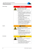
Page 18: ...2 6 1 Danger symbols on the MHTMTM MicroDrive barrier The relevant dangerous areas on the barriers can be identified by the following pictograms Electric voltage DANGER Mortal danger by electric volt...

Page 19: ...e observed and complied with Electric voltage DANGER Mortal danger by electric voltage Touching live parts can be lethal Damage to the insulation or to individual components can be lethal Switch off t...

Page 20: ...torms Protect yourself in buildings or vehicles Improper operation WARNING Danger from improper operation of the barrier Improper operation of the barrier can cause severe or lethal injuries The barri...

Page 21: ...persons and animals must be excluded Marking the danger area by prohibition signs for persons bicyclers etc If required set up barriers such as fences and railings If required set up separate passagew...

Page 22: ...ghts Carrying and lifting the barrier arm and housing from the pallet should be done by at least two people Heavy weight WARNING Risk of injury when lifting heavy objects alone The weight of heavy obj...

Page 23: ...Danger of crushing at opened barrier housing at the lever system and flange shaft The lever system and the flange shaft in the barrier housing can cause serious crushing injuries Only skilled personne...

Page 24: ...05 Illegible signage CAUTION Risk of injury by illegible symbols Labels and signs can become dirty or unrecognisable in the course of time Always keep safety warning and operating notes in a good rea...

Page 25: ...or closes When a barrier opens or closes the barrier arm may lead to severe crushing or injury Keep a distance of at least 2 ft 610 mm between the barrier arm and other objects such as walls masonry o...

Page 26: ...ttachment Fig 3 Type plate 1 Type code 2 Serial number 3 Power supply Frequency 4 Nominal current consumption max peak current consumption additional current consumption when using the service socket...

Page 27: ...t lang PARKING Magnetic Parking PARING PRO Magnetic Parking Pro PARKING SEL Magnetic Parking Select 14 15 L Left version R Right version 16 A Standard wide range 85 264 V AC 47 63 Hz C UL version US m...

Page 28: ...nge Control Unit Parking VarioBoom Vario flange MGC Parking Pro VarioBoom Vario flange MGC Pro Parking Sel VarioBoom Vario flange MGC Pro Access VarioBoom Vario flange MGC Access L VarioBoom Vario fla...

Page 29: ...4 1 1 Dimensions and weight Fig 4 Dimensions barrier system and barrier arm profile Access series Dimensions in inch or feet are without parenthesis Dimensions in mm are in parenthesis 1 Object such a...

Page 30: ...0 5 1 5 0 5 Max peak current consumption 2 A 2 5 2 5 3 5 3 0 3 5 3 0 Nominal power consumption 1 W 25 50 95 25 95 25 Duty cycle 100 1 The values refer to a power supply of 120 V AC 60 Hz and without a...

Page 31: ...Access and Parking Technical data 5815 5013US Version 05 31 4 1 4 Operating times Designation Unit Access Access Pro Access Select L L L Opening time Closing time s 2 2 4 0 1 3 4 0 1 3 4 0 Table 5 Ope...

Page 32: ...ensions and weight Fig 5 Dimensions barrier system and barrier arm profile Access Pro H series Dimensions in inch or feet are without parenthesis Dimensions in mm are in parenthesis 1 Object such as w...

Page 33: ...0 5 Max peak current consumption 2 A 3 0 3 0 3 0 Nominal power consumption 1 W 25 25 25 Duty cycle 100 1 The values refer to a power supply of 120 V AC 60 Hz and without accessories 2 The values refe...

Page 34: ...rive Access and Parking Technical data 34 5815 5013US Version 05 4 2 4 Operating times Designation Unit Access Pro H ft m 12 3 66 14 4 3 20 6 00 Opening time Closing time s 4 0 4 0 4 0 Table 9 Operati...

Page 35: ...ensions and weight Fig 6 Dimensions barrier system and barrier arm profile Parking series Dimensions in inch or feet are without parenthesis Dimensions in mm are in parenthesis 1 Object such as wall b...

Page 36: ...35 95 95 Duty cycle 100 1 The values refer to a power supply of 120 V AC 60 Hz and without accessories 2 The values refer to a power supply of 120 V AC 60 Hz with illumination service socket not used...

Page 37: ...ngth without overvoltage module 1 ft m 100 30 Digital outputs Number 4 open collector Switching voltage V DC 24 10 Max switching current mA 100 Max line length without overvoltage module 1 ft m 100 30...

Page 38: ...Number of induction loop sensitivity levels 10 levels Response sensitivity induction loop Selectable 0 01 to 2 0 Table 15 Plug in module Detector A B 4 6 Plug in module Radio Designation Unit Plug in...

Page 39: ...ction 5 1 Design 5 1 1 Access and Parking Fig 7 Barrier system design series Access and Series Parking 1 Barrier housing 2 VarioBoom barrier arm 3 Pendulum support from 15 ft 4 57 m barrier arm length...

Page 40: ...S Version 05 5 1 2 Access Pro H Fig 8 Design barrier series Access Pro H 1 Barrier housing 2 MicroBoom Access Pro H 3 Pendulum support from 15 ft 4 57 m barrier arm length 4 Empty conduits for mains c...

Page 41: ...sition of the barrier arm and thus serve the control unit to control the best acceleration and deceleration For the series Access and Parking the angled barrier arm VarioBoom is used this barrier arm...

Page 42: ...should be done by a minimum of two people Heavy weight WARNING Risk of injury when lifting heavy objects alone The weight of heavy objects can severely injure a person Lifting and carrying the barrie...

Page 43: ...n Immediately check the delivery after receipt for completeness and transport damages Proceed as follows in the case of outwardly recognisable transport damage Do not accept the delivery or only under...

Page 44: ...ten the barrier housing and barrier arm prior to transport e g screw it onto a pallet Transport and put down barrier housing and barrier arm with a forklift and lift with suitable lifting gear 6 4 Sto...

Page 45: ...will be covered by the metal part is The induction loops must not respond to persons or objects with a small metal portion like a bicycle for instance Safety loops must secure the danger area undernea...

Page 46: ...loop Fig 10 Passenger car loops passage with long opening loop 1 Safety loop 2 Opening loop 3 Barrier Due to a long opening loop vehicles can drive through without needing to stop Arrangement of truc...

Page 47: ...ing direction of the inner safety loop for passenger cars must be identical to the outer safety loop for trucks Meaning the sensitivity in the middle between outer and inner loop is then at its maximu...

Page 48: ...sageway during the entire path of travel of the vehicular barrier Danger of crushing and shearing barrier arm WARNING Danger of crushing and shearing when the barrier opens or closes When a barrier op...

Page 49: ...sure that there is sufficient assembly space Pay attention to tidiness and cleanness at the assembly site Loosely stacked or lying around components and tools are accident sources Comply with specific...

Page 50: ...ty conduits Installing induction loops The following procedures have to be observed during assembly and installation Unpack barrier and accessories Mount barrier housing on the foundation Remove trans...

Page 51: ...of at least 2 ft 610 mm between the barrier arm and other objects such as walls masonry or houses See page 25 chapter 2 7 2 Optional Light barrier post place post at a distance of at least 2 ft 610 m...

Page 52: ...page page 51 Fig 13 and page 53 Fig 14 Have sufficient load carrying capacity concrete foundations C35 45 XD3 XF2 Water cement value 0 5 Foundation depth at least 31 5 in 800 mm frost protected founda...

Page 53: ...connection empty conduit for loop connection diameter 1 14 in 29 mm 3 Empty conduit for induction loop diameter 1 14 in 29 mm 4 Empty conduit for control lines diameter 1 14 29 mm 5 Concrete foundati...

Page 54: ...s Sikagard 703 W or deepdry to the concrete surface before housing assembly Moisture protection prevents entering of moisture into the housing from the concrete floor 8 3 2 Foundation and empty condui...

Page 55: ...for light barriers Empty conduit for receiver connection line 4 Foundation depth at least 800 mm frost protected foundation depth to be adjusted to the local situation 1 Dig foundation hole pursuant...

Page 56: ...ns for the assembly and installation of induction loops On barriers with an automatic closing function induction loops are used for the detection of vehicles The loop underneath the barrier arm always...

Page 57: ...p heating etc in the roadway the induction loop must have a clearance of at least 1 97 in 50 mm from those Metals in the proximity of the induction loop affect the response sensitivity Avoid direct co...

Page 58: ...t loop cables strands must be used 8 4 3 Testing induction loops To verify the contact resistance insulation resistance and inductance of the loop these properties must be measured after installation...

Page 59: ...duction loop according to chapter 8 4 3 6 We recommend to cover the inserted loop using quartz sand Make sure that at least 0 98 in 25 mm remain between the upper edge of the roadway and the quartz sa...

Page 60: ...are in parenthesis 1 Barrier housing 2 Paving 3 Loop cable 4 Sand bed 5 Substructure When installing induction loops under interlocking stone paving following points must be observed additionally Use...

Page 61: ...3 Lay down barrier arm 4 Unpack and lay out accessories 5 Separate material according to type and size and recycle them after use 8 6 Open barrier housing Drive system balancing springs connection te...

Page 62: ...13 6 Mounting profile 7 Foundation anchor 8 Foundation 9 Silicon sealant 2 Drill holes for the foundation anchors according to the foundation plan page 53 Fig 14 in compliance with the indicated sizes...

Page 63: ...rs installation requirements Assemble light barrier post 1 The foundation must have cured 2 Drill holes for the foundation anchors according to the foundation plan page 55 Fig 16 in compliance with th...

Page 64: ...are without parenthesis Dimensions in mm are in parenthesis A View A B View B C Light barrier housing transmitter 1 Hexagon socket screws 5 AF 2 Transmitter 3 Transmitter connection line 4 Cable screw...

Page 65: ...ost B Light barrier housing 1 Gap 2 Drill holes for blind rivet nut 3 Hexagon socket screws 5 AF 4 Receiver 5 Receiver connection line 1 Press the two blind rivet nuts into the two intended bores at t...

Page 66: ...arrier arm profile to both connection plates with the 4 Torx The larger bores must remain free 5 Attach the two half shells with the washers and the hexagon socket screws 8 11 Assemble edge protection...

Page 67: ...e further edge protections into the intended groove until the edge protection ends flush with the barrier arm 8 12 Assembling flange and barrier arm Danger of injury CAUTION Danger of injury There is...

Page 68: ...from the barrier arm Fig 24 Disassemble end cap 6 Slide the shorter slot unit and the additional sheet into the groove on the barrier room bottom Fig 25 Installing the lower slot nut and additional s...

Page 69: ...rusion of the flange must point towards the barrier arm end Tighten screws twice in sequence to ensure that all screws are tightened correctly Torque wrench with Torx T40 Tightening torque 11 8016 lbf...

Page 70: ...ht through the upper tool bore with a tool to press the lever arm from the dead point See page 119 chapter 12 5 14 If required check the vertical alignment of the barrier arm and correct with the hexa...

Page 71: ...rsion and right version See type code page 27 and as of page 29 Fig 4 to Fig 6 If required you can also remove the barrier arm yourself from one side of the barrier housing and replace it on the other...

Page 72: ...ier arm Fig 31 Disassemble flange with barrier arm Move flange shaft 9 Remove the v ring from the flange shaft Fig 32 Remove the v ring 10 Slightly loosen the two hexagon socket screws 10 AF of the cl...

Page 73: ...lange shaft Torque wrench with hexagon socket 10 AF Tightening torque 88 508 lbf ft 120 Nm 15 Hook in the balancing springs in the lever system 16 Slip the v ring over the flange shaft The sealing lip...

Page 74: ...rm and correct with the hexagon socket screws at the flange if necessary 25 Switch on power supply 26 Switch the Service switch on the control unit The LED lights red The display backlighting flashes...

Page 75: ...that exactly balance the barrier arm weight These balancing springs are pre set in the factory The precise setting must be performed after assembly of the barrier arm and before commissioning The leve...

Page 76: ...ith barrier tape WARNING Danger of crushing between barrier arm and barrier housing 2 Switch off power supply Ensure that the system is powered down Secure against reactivation 3 Place barrier arm in...

Page 77: ...or 7 Adjust springs with a wrench via the screws with locknuts The barrier arm lowers The spring force is too low The barrier arm pulls up The spring force is too strong The barrier arm has come to re...

Page 78: ...9 to 5 6 ft 1 5 to 1 7 m 1 5 9 to 7 6 ft 1 8 to 2 3 m 2 7 9 to 9 5 ft 2 4 to 2 9 m 3 9 8 to 11 2 ft 3 0 to 3 4 m 4 11 5 to 12 8 ft 3 5 to 3 9 m 5 13 1 to 14 1 ft 4 0 to 4 3 m 6 14 4 to 15 1 ft 4 4 to...

Page 79: ...t 3 7 to 4 0 m 5 13 5 to 14 4 ft 4 1 to 4 4 m 6 14 8 to 15 4 ft 4 5 to 4 7 m 7 15 8 to 16 7 ft 4 8 to 5 1 m 8 17 1 to 18 1 ft 5 2 to 5 5 m 9 18 4 to 19 7 ft 5 6 to 6 0 m 7 2 Table 19 Overview table ba...

Page 80: ...8 14 3 Equipment plan balancing springs The balancing springs are aligned as follows for the barriers MAGNETIC MHTM TM MicroDrive Access and Parking Fig 36 Equipment plan balancing springs 1 Front 2 B...

Page 81: ...nly slightly Tighten the attachment screws again after alignment Alignment conditions for light barrier Transmitter and receiver of the light barrier must be aligned with each other for an object to b...

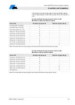
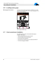
Page 82: ...rier where easily visible Two warning signs for the barrier are part of delivery Fig 37 Apply prohibition signs 8 17 Check assembly and installation The following points must be checked after assembly...

Page 83: ...trical system Electrical specialists are able due to their technical training knowledge and experiences as well as knowledge of the relevant standards and regulations to execute tasks on electrical sy...

Page 84: ...from live parts Moisture or dust may cause a short circuit If the electrical connection is established during precipitation e g rain or snow penetration of moisture must be prevented by suitable meas...

Page 85: ...ectro magnetic environmental conditions may cause interferences or malfunctions Place control lines and mains cables into separate conduits Use cables according to the electrical circuit plan Only ins...

Page 86: ...DANGER Danger to life from electric shock If the mains supply is not connected to the terminal clamps correctly loosens from the terminal clamps and touches the housing or door there is a direct dang...

Page 87: ...f the mains supply Dimensions in inch or feet are without parenthesis Dimensions in mm are in parenthesis 1 Phase 2 Neutral conductor 3 Ground conductor Mains supply placement 3 Connect mains supply t...

Page 88: ...relays are change over contacts DANGER Mortal danger by electric voltage 1 Disconnect barrier system supply voltage Ensure that there is no voltage applied Secure against reactivation Connecting the c...

Page 89: ...t safety loops or safety light barriers to the control unit Safety loops must only be connected to monitor vehicles Only MAGNETIC safety light barriers must be used If you connect a safety loop the ba...

Page 90: ...by a vehicle or person within three barrier openings In operation the number is increased to ten barrier openings If the plausibility check fails the barrier is decommissioned for reasons of safety T...

Page 91: ...ment Description of control units MGC and MGC Pro for MHTM TM MicroDrive barriers Fig 42 Connecting safety loop 1 Control unit 2 Connection of induction loop A 3 Plug in module Detector 1 A B 4 Connec...

Page 92: ...r housing Alternatively the receiver can also be installed to an opposite barrier housing Fig 43 Use reflective foil 1 Receiver covered by reflective foil 2 Reflective foil 3 Transmitter 1 There must...

Page 93: ...and receiver The following items must be met The yellow LED at the receiver must go out The barrier cannot be closed 9 4 5 Connecting emergency opening contacts Fire fighter switch emergency opening...

Page 94: ...Pro H Access Select and Access Select L Parking Pro and Parking Select For the remaining barrier types the control unit MGC is installed Here the inputs are firmly assigned For input parameterisation...

Page 95: ...ect and Access Select L Parking Pro and Parking Select For the remaining barrier types the control unit MGC is installed Here the outputs are firmly assigned For output parameterisation see separate d...

Page 96: ...lectrical protective devices installed 2 pole main switch circuit breaker and ground fault circuit interrupter Is the power cable connected to the terminal in compliance with chapter 9 3 Are the induc...

Page 97: ...observe the radius of action of the barrier arm Prior to start of works ensure that all housing covers are correctly mounted Wind forces over 10 Beaufort WARNING Risk of injury from breaking off barr...

Page 98: ...f required Inspection during the first start up The following inspections must be performed prior to first start up Check programme mode See separate document Description of control units MGC and MGC...

Page 99: ...u switch the mains voltage on again Fig 44 Switching on and off the barrier 1 Service socket WARNING Service socket is live also when mains switch is switched off 2 Double pole mains switch Switching...

Page 100: ...rs chapter Power failure 5 Mount the door 6 Attach and lock the hood 10 4 Opening and closing the barrier manually You can only open and close the barrier manually in the Service mode Fig 45 Service s...

Page 101: ...position The moving barrier arm can severely injure a person Keep supplying the barrier with mains voltage Remove the barrier arm if necessary NOTICE Possible damage to the equipment by condensed wate...

Page 102: ...trician Prior to work ensure that there is sufficient assembly space Pay attention to tidiness and cleanness at the assembly site Loosely stacked or lying around components and tools are accident sour...

Page 103: ...vals 11 4 Clean barrier housing from the inside Carrying out cleaning work 1 Switch off power supply and secure against restarting DANGER Mortal danger by electric voltage Keep moisture and dust away...

Page 104: ...t Visual inspection of foundation anchors mounting profiles and mounting material for corrosion Remove corrosion damage Specialist Visual inspection of the barrier arm for damage and corrosion Clean t...

Page 105: ...on loops function See separate document Description of control units MGC and MGC Pro for MHTM TM MicroDrive barriers chapter Detector 1 A B Check the induction loops Measure the contact resistance ins...

Page 106: ...ty and special dangers General WARNING Danger of injury from inappropriate troubleshooting Inappropriate troubleshooting can cause severe or lethal injuries All troubleshooting work must be performed...

Page 107: ...arm 12 2 Malfunction table barrier malfunctions For requirements to the MHTM MicroDrive service specialist see page 17 chapter 2 4 1 Malfunction Display is difficult or impossible to read Possible cau...

Page 108: ...g springs of the lever system set too weakly for the barrier arm weight Adjust balancing springs See page 75 chapter 8 14 MHTM MicroDrive service specialist Malfunction Barrier does not close The mess...

Page 109: ...Removal by Opening command is active Cancel the opening command Electrical specialist Induction loop reports engaged although no vehicles are present Check and if necessary adjust loop frequencies Mea...

Page 110: ...on the safety loop Possible cause Corrective action Removal by Option monitoring for the parameters Mode A or Mode B not selected in the menu Loop detector 1 A B Select option Monitoring MHTM MicroDri...

Page 111: ...s on the display The control unit differentiates between events warnings and errors The corresponding message is displayed Event messages INFO Event messages inform about events such as switching to b...

Page 112: ...logic control and detector module impaired Perform reset See page 118 chapter 12 4 Check plug contacts Clean plug contacts with spirit Observe ESD provisions Replace the control unit FF03 ERROR Monito...

Page 113: ...F08 INFO Mains operation active again after battery mode The barrier is supplied with mains voltage again FF09 INFO Reduced opening angle In some barrier types the opening angle can be mechanically li...

Page 114: ...rform any reference run Check motor communication Check mechanics Perform reset See page 118 chapter 12 4 8130 WARNING Note monitoring Communication with a plug module was interrupted Check if all plu...

Page 115: ...Check the balancing spring settings If required remove heavy attachments from the barrier boom If required contact Service 4210 WARNING Overtemperature A high temperature was recognised Check motor t...

Page 116: ...cing springs and mechanics 7510 ERROR Motor communications error Communication between motor and control impaired or interrupted Verify cables Contact service if required FF32 ERROR HW Enable Test fai...

Page 117: ...loop is connected select the option Inactive in the menu Detector FF4C WARNING Loop error B or D Short circuit or idle loop B or D Remove loop error and perform adjustment If no loop is connected sele...

Page 118: ...rformed as follows Switch of power supply and switch it on again after 10 seconds or Press the two middle operating buttons on the control unit display for 5 seconds NOTICE Damage to the unit by too s...

Page 119: ...oved manually In this case proceed as follows 1 Remove the barrier housing hood 2 Remove the barrier housing door 3 Press a tool straight into appropriate tool bore The lever arm is pressed from the d...

Page 120: ...NETIC Procure spare parts from your dealer or directly from the manufacturer For the address see invoice delivery note or the reverse of these instructions After completion of repair work ensure that...

Page 121: ...f injury There is a danger of injury when mounting the barrier arm Barrier arms as of a length of 14 8 ft 4 5 m must be installed by two persons We recommend also installing shorter barrier arms with...

Page 122: ...F at the flange 6 Remove the flange with the barrier arm Fig 47 Disassemble flange with barrier arm Disassemble flange 7 Remove flange from the barrier arm For this loosen the 4 Torx screws at the bar...

Page 123: ...ot nut 2 Additional sheet 11 Place the longer slot nut on the upper side of the barrier arm Fig 51 Installing the upper slot nut 12 Attach the flange with the 4 Torx screws to the barrier arm The shor...

Page 124: ...t through the upper tool bore with a tool to press the lever arm from the dead point See page 119 chapter 12 5 18 If required check the vertical alignment of the barrier arm and correct with the hexag...

Page 125: ...ecycled according to material types Non recyclable materials have to be disposed of in an environmental friendly manner Decommissioning disassembly and disposal of the barrier may only be carried out...

Page 126: ...Barrier MHTM TM MicroDrive Access and Parking 126 5815 5013US Version 05...

Page 127: ...ed by UL in accordance with the Standard s indicated on this Certificate Standard s for Safety UL 325 Door Drapery Gate Louver and Window Operators and Systems C22 2 No 247 Operators and Systems of Do...

Page 128: ...ertify that representative samples of the product as specified on this certificate were tested according to the current UL requirements Vehicular Barrier Gate Operators Series ACCESS ACCESS PRO and AC...

Page 129: ......

Page 130: ...Barrier MHTM TM MicroDrive Access and Parking 130 5815 5013US Version 05...

Page 131: ...ccess and Parking Appendix 5815 5013US Version 05 131 17 Appendix 17 1 Wiring diagrams Following wiring diagrams apply to standard barriers Observe the customer specific wire diagrams for customer spe...

Page 132: ...Barrier MHTM TM MicroDrive Access and Parking Appendix 132 5815 5013US Version 05...

Page 133: ...5 2 1 2 3 4 5 6 7 8 9 0 04 13 08 12 5K12530 gp 05 29 10 12 5K12538 gp 06 26 02 13 5K13503 gp 22 02 2013 gp Date Name Modification project Version controller Light barrier Transmitter Option loops Opti...

Page 134: ......

Page 135: ...50 60Hz main switch service socket main terminals block 1 2 3 4 S1 3460 5098 Option to mounting panel 2 Option 1 2 3 4 S2 3046 5098 Option M supply voltage motor motor Interface cable Power supply uni...

Page 136: ......

Page 137: ...r passage A signal light B Option open low priority external Opening loop Exit close open with vend count open high priority close open low priority closed Common Relais 1 3 loop active A Common Relai...

Page 138: ......

Page 139: ...on LS01 0 04 13 08 12 5K12530 gp 05 29 10 12 5K12538 gp 06 26 02 13 5K13503 gp 22 02 2013 gp Date Name Modification project Version option receiver transmitter BK BU BN BN BN WH n c BK BU BN WH n c BK...

Page 140: ......

Page 141: ...g 103 Commissioning 98 Connecting mains supply 86 Control unit Technical data 37 Control unit MGC 9 Control unit MGC Pro 9 Copyright 11 Customer service 12 D Danger area 25 Decommissioning 125 Tempora...

Page 142: ...39 Technical data 35 Passenger car loops 45 46 Pendulum support 39 40 Personal protective equipment 18 Pictogram explanation 10 Plausibility check Procedure 90 R Radio plug in module Technical data 3...

Page 143: ...Barrier MHTM TM MicroDrive Access and Parking Index 5815 5013US Version 05 143 W WARNING 111 Warning messages WARNING 111 Warning notes 10 Warning signs 82 Warnings 111 Warranty 12...

Page 144: ...MAGNETIC Automation Corporation 3160 Murrell Road Rockledge Florida 32955 USA Tel 1 321 635 8585 Fax 1 321 635 9449 E Mail info ac magnetic com Internet www ac magnetic com Address sales partner...

Reviews: