Pedestrian Barrier High Door MPH 112
Assembly and installation
36
5817,5005EN / Version 01
1
3
4
4
4
3
5
6
B
Standard
A
Wide
7
2
2
2
ENTR
Y
EXIT
C/
A
Standard
E/B
Wide
820
930
1430
233
520
520
910
233
200
80
20
X
Y
X
Mag55175167
Master
Master
Master
Slave
Slave
Slave
3
Y
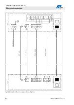
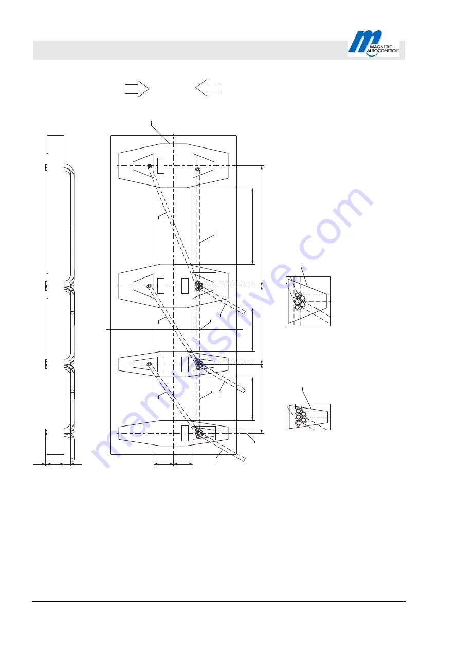
Fig. 9: Foundation plan and layout for empty conduits
1
Mains to the master
2
External control wiring to the master
3
Empty conduits master – slave, d min = 40 mm
4
Empty conduits to the card reader d min = 30 mm
5
Boundary of the "Standard" module
6
Boundary of the "Wide" module
7
Foundation, recommended distance approx. 110 mm
B End
module
"Standard"
C/A Center module "Standard" or End module "Standard"
E/B Transition module "Standard – Wide" or
End module "Wide"
A
Basic module "Wide"
Put data lines and mains cables into separate conduits.
module


