Pedestrian Barrier High Door MPH 112
Electrical connection
5817,5005EN / Version 01
53
8.3.1
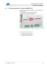
Digital inputs
All inputs galvanically isolated by optocouplers
Input voltage 24V ±10%
Input current 10 mA per input
Impulse length for inputs 100 ms – 300 ms
Input
Function
Description
1
Deactivate motor end-
stages in case of
emergency
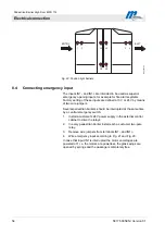
This input permits to power of the motor end-stages in
case of an emergency. The glass wings are pulled open
by springs then. The input is fail-safe, i.e. the pedestrian
barrier is only operative when a continuous signal is
present. Refer also to Page 57.
2
Opening input entry side
At this input, the barrier can be opened by a card reader,
for example, indicating a valid passage on the entry side.
Refer also to Page 57.
3
Opening input exit side
At this input, the barrier can be opened by a card reader,
for example, indicating a valid passage on the exit side.
Refer also to Page 57.
4
Light barrier LS 1
5
Light barrier LS 2
The two light barriers LS 1 and LS 2 are evaluated
together to permit direction detection of a passage. They
are in front of the card reader on the entry side of the
pedestrian barrier.
6
Light barrier LS 5
7
Light barrier LS 6
The two light barriers LS 5 and LS 6 are evaluated
together to permit direction detection of a passage. They
are in front of the card reader on the exit side of the
pedestrian barrier.
8
Safety light barrier LS 3A
and LS 3B
The light barriers LS 3A and LS 3B work in parallel. They
provide a security monitor close to the glass wings. In
combination with safety light barriers LS 4A and LS 4B,
they also serve to detect a completed passage with
ensuing closure of the glass wings.
9
Safety light barrier LS 4A
and LS 4B
The light barriers LS 4A and LS 4B work in parallel. They
provide a security monitor close to the glass wings. In
combination with safety light barriers LS 3A and LS 3B,
they also serve to detect a completed passage with
ensuing closure of the glass wings.
Table 7: Digital inputs

