Pedestrian Barrier High Door MPH 112
Configuration of pedestrian barrier
64
5817,5005EN / Version 01
10.3 Selecting the operating mode
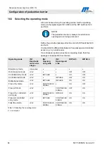
All in all choose among 10 operating modes. Set the operating
mode via the digital inputs IN1 to IN3 and the DIP switches S2.3
and S2.4.
NOTE!
The pedestrian barrier is always closed when no
opening pulse is being processed.
Define the permitted passage direction via both DIP switches S2.3
and S2.4.
It is important to differentiate between free passage and controlled
access, e.g. by a card reader.
If a continuous signal is present at an opening input, then free
passage is activated for this direction.
Operating mode
IN1
Deactivate
motor end-
stages
IN2
Opening
entry side
IN3
Opening exit
side
DIP S2.3
DIP S2.4
Emergency mode
Interrupted
x x x x
Out-of-service mode
+24V x
x
OFF OFF
Controlled entry mode
+24V IMPULSE
x
ON OFF
Controlled exit mode
+24V x
IMPULSE
OFF ON
Bidirectional mode
+24V IMPULSE
IMPULSE
ON ON
Free entry mode
+24V
CONTINUOUS
SIGNAL
x ON
OFF
Free exit mode
+24V x
CONTINUOUS
SIGNAL
OFF ON
Free entry, controlled
exit mode
+24V
CONTINUOUS
SIGNAL
IMPULSE ON
ON
Free exit, controlled
entry mode
+24V IMPULSE
CONTINUOUS
SIGNAL
ON ON
Fully-free mode
+24V
CONTINUOUS
SIGNAL
CONTINUOUS
SIGNAL
ON ON
Table 12: Selecting the operating mode
X non-relevant

