Pedestrian Barrier High Door MPH 112
Electrical connection
5817,5005EN / Version 01
49
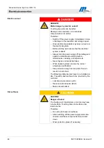
Personal protective equipment
The following must be worn during all installation work:
Work clothes
Protective gloves
Safety shoes.
8.2
Electrical connection
The end housings must be dismantled. Refer to Page 38.
1. Earth system. Connect barrier modules with each other by
using the earthing clamps.
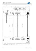
2. Connect the mains cable to every centre and end module
according to wiring diagram. Refer to Page 20, Fig. 19 and to
Page 106.
3. Connect low-voltage cables and data cable (CAN bus)
according to wiring diagram. Use shielded cables.
Refer also to Page 50, Fig. 19.
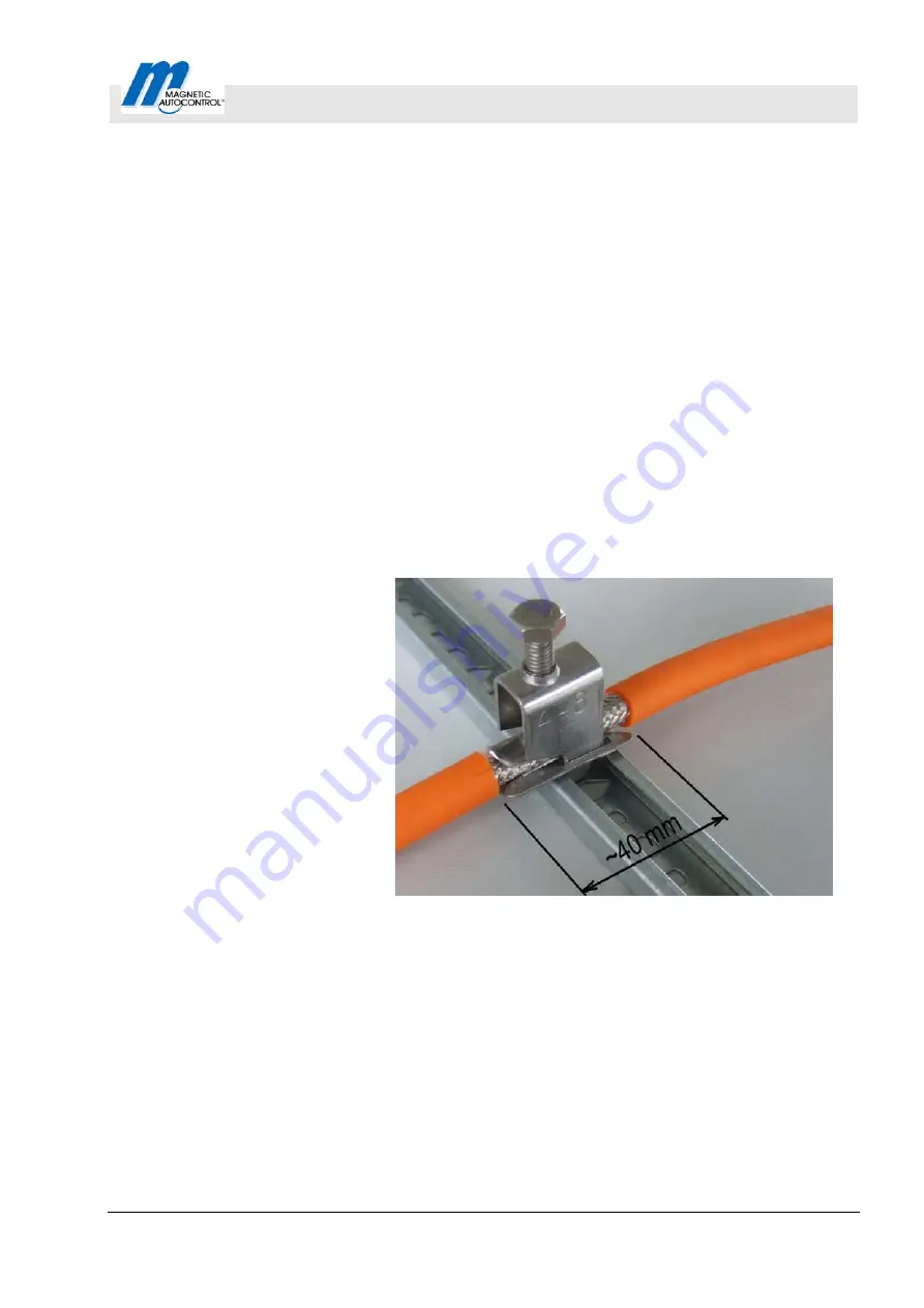
4. Connect the cable shields of both ends of the shielded cables
to EMC clamps on the mounting plates.
Fig. 18: Assembly EMC clamp


