7
IV. BASIC MAGNETIZER CIRCUIT DESCRIPTION
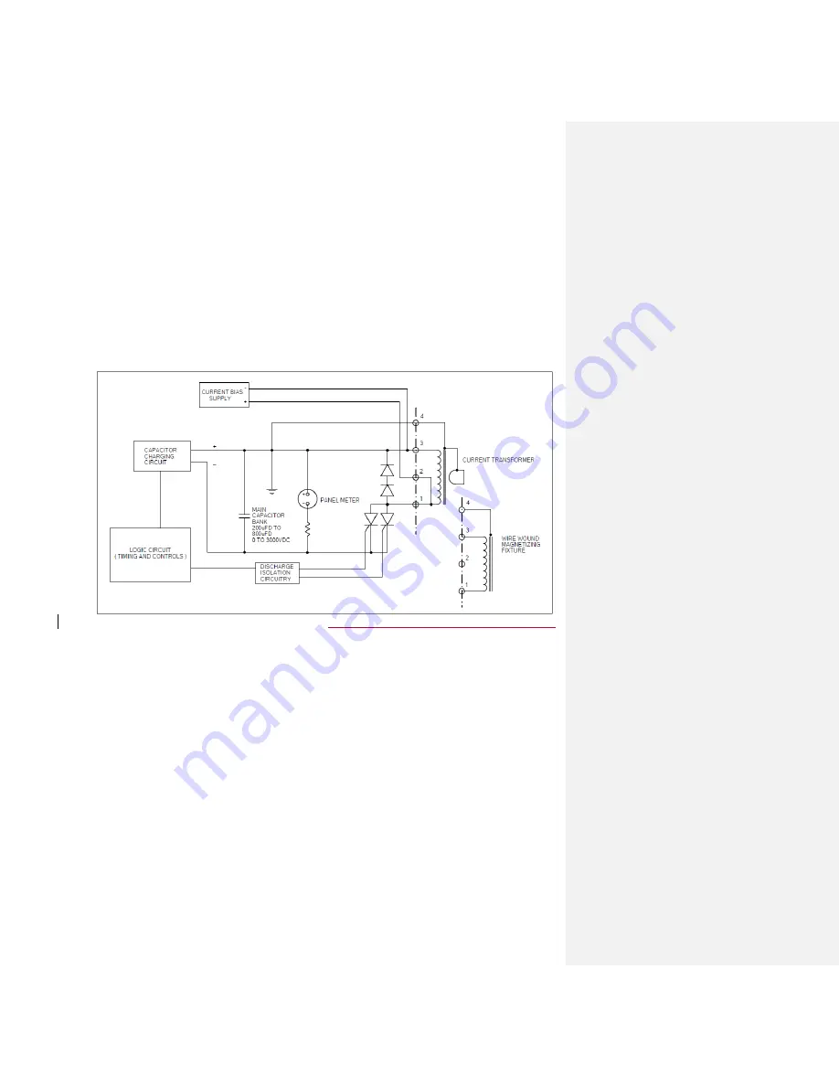
A Capacitive Discharge Magnetizer functions by supplying large amounts of energy in a
short time to a Magnetizing Fixture. This magnetizing pulse is milliseconds in length and
is drawn through a discharge switch from the capacitor bank. The capacitor bank is
charged by drawing small amounts of power from the power line over several seconds.
The basic magnetizer consists of a capacitor charging and discharging circuit both of
which are controlled by the logic circuit within the cabinet. A current bias supply is
provided for use with current transformers to make use of the maximum possible flux
change and, therefore, the greatest energy transfer for each size of current transformer.
B
lock diagram of the Model 942B Magnetizer
Note: All of the major components’ circuit designations in the following section of this
manual are in bold and correspond to the Electrical Schematics sheet 4 and 5 of the
drawing set.
A. Capacitor Charging Circuit
The capacitor charging circuit consists of a Solid State Relay (
1SSR
), Current Limiting
Inductors (
1L and 2L
), Step-up Transformers (
1T and 4T
), Rectifier Boards (
1SA and
2SA
), and the Capacitor Bank (
1C thru 8C
). The charging circuit is controlled by the
Solid State Relay providing primary power to the Step-up Transformers through the
Current Limiting Inductors. The secondary voltage of these transformers is rectified by
the Rectifier Boards that are connected directly to the Capacitor Bank.
Summary of Contents for 942B
Page 2: ......
Page 25: ...18 NOTES...


