background image

60

Control unit MGCplus

Description of menus and parameters

6.4.2.2 

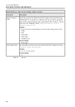
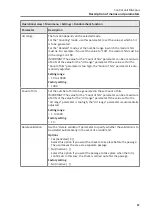
In direction 2

Operational view > Main menu > Information > People counter > In direction 2

Parameter

Description

Passages total

Shows the number of all validated and non-validated passages in direction 2.

Valid. passages

Shows the number of all validated passages in direction 2.

Reverted

Shows the number of people who have entered and exited the pedestrian 

gate on one side.

Intrusion

Shows the number of unauthorized access attempts of the "Intrusion" type 

in direction 2.

Wrong direction

Shows the number of unauthorized access attempts of the "Wrong direc-

tion" type in direction 1.

Tailgating

Shows the number of unauthorized access attempts of the "Tailgating" type 

in direction 2.

Table 36: 

People counter – In direction 2

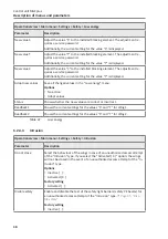
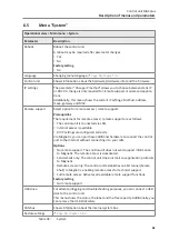
6.4.3 

Light barriers (PE beams)

Operational view > Main menu > Information > Light barriers (PE beams)

Parameter

Description

Occupied

Shows the light barriers (PE beams) that are currently occupied.

Warning

Shows the light barriers (PE beams) that are currently occupied for too long. 
The warning time is adjusted using the "Warning light barriers (PE beams)" 

parameter

ä

 Page 52, "Warning light barriers (Parameter)".

If one of the light barriers (PE beams) is occupied for longer than the set 

time, the output "Warning light barriers (PE beam)" is set. 

ä

 Page 28, 

"Warning light barriers (Output)".

Prerequisites

 ›

"Warning light barriers (PE beams)" parameter: > 0 s 

Table 37: 

Light barriers (PE beams)

Summary of Contents for MGCplus

Page 1: ...Description Pedestrian gate mWing MHTM FlowMotion Control unit MGCplus Doc ID 5817 0033EN Version 00...

Page 2: ...2 Control unit MGCplus MAGNETIC AUTOCONTROL GMBH Grienmatt 20 D 79650 Schopfheim Germany Phone 49 7622 695 5 Fax 49 7622 695 802 info magnetic germany com www magnetic access com...

Page 3: ...control unit 15 3 3 Special operating modes 16 3 4 Control of the passages with Control direction 1 and or Control direction 2 17 3 4 1 Explanations 17 3 4 2 Parameter Control variant Option Variant...

Page 4: ...direction 49 6 2 4 5 Tailgating 50 6 2 5 Safety 51 6 2 5 1 Forced opening 51 6 2 5 2 Lock wings autom 51 6 2 5 3 Warning light barriers PE beams 52 6 2 6 Signalling 52 6 2 6 1 Buzzer 52 6 2 6 2 GED no...

Page 5: ...tion 64 7 1 Safety in troubleshooting 64 7 2 Malfunctions pedestrian gate 65 7 3 Event warning and error messages in the display 66 7 3 1 Event warning and error messages Logic control Control unit 67...

Page 6: ...6 Control unit MGCplus...

Page 7: ...name and the firmware ver sion FW Version are displayed in the Firmware menu System Control unit Firmware Firmware ID Version 49160013 mWing 1 0 0 Table 1 MGCplus control unit firmware version IMPORTA...

Page 8: ...nts as well as bodily injuries and property dam age Warning Notes DANGER The signal word DANGER points to an immediately dangerous sit uation which leads to death or severe injuries if it is not avoid...

Page 9: ...well as information for an efficient and trou ble free operation 1 2 2 Abbreviations used Abbreviation Description Contr Controlled OM Open mode D1 Direction 1 passage direction 1 D2 Direction 2 passa...

Page 10: ...ant mechanic plant fitter assembly mechanic assembly fitter or has a comparable technical education Has completed training as an electrical safety expert Has additional knowledge and experience Knows...

Page 11: ...1 Paid MGCplus Master PE receiver Slave PE transmitter 1 2 3 4 4 5 5 1 6 3 Fig 1 Position of the light barriers PE beams and definitions shown here is C module see following page for descriptions 1 S...

Page 12: ...to the passage direction from the Unpaid zone to the Paid zone Table 4 Definitions 2 2 Unauthorised access attempts The control unit differentiates between different kinds of unauthorised access attem...

Page 13: ...is closed No validations are accepted in any di rection No passage is possible If a person enters the pedestrian gate the control unit interprets this as an unauthorised access at tempt Contr D1 Close...

Page 14: ...time Only then can a person pass the pedestrian gate in direction 2 Free D1 Contr D2 Free direction 1 Controlled direction 2 See description Contr D1 Free D2 but in reverse Free D1 D2 Free direction 1...

Page 15: ...unctions are only effective in the following cases The function Control di rection 1 is assigned to an input or the function Control direction 2 is as signed to an input or the functions Control direc...

Page 16: ...control unit of the pedestrian gate must be reset If the critical error continues to appear a service technician is required Emergency mode If an input is set with the Emergency open function or if a...

Page 17: ...n the corresponding direction is possible Parameter Control variant Use this parameter to select the mode for the Control direction 1 Control direction 2 and Control open mode inputs Variant 1 This va...

Page 18: ...ase also note the parameter descriptions Control variant and Delay permanent open The following symbols and abbreviations are used in the tables Symbol Description Set Not set Not relevant OM Open mod...

Page 19: ...not set to set at in put Control direction Permanent signal at in put Control direction Resulting operating mode Resulting control unit behaviour 1 2 1 2 1 2 Invalid This variant is available in the f...

Page 20: ...direction 2 can be performed the passage in direction 1 must be com pleted Contr D1 Free D2 Process passage in direction 1 Before the validated passage in direction 1 can be performed the passage in...

Page 21: ...Control variant Input Con trol direction Validation by changing from not set to set at in put Control direction Permanent signal at in put Control direction Resulting operating mode Resulting control...

Page 22: ...irection 2 can be performed the passage in direction 1 must be com pleted Contr D1 Free D2 OM Process passage in direction 1 Before the validated passage in direction 1 can be performed the passage in...

Page 23: ...inputs you assign certain functions to the inputs Exam ple If you parameterise the Emergency open function for input IN1 you must connect a fire alarm signal to this input If the signal is interrupted...

Page 24: ...every state change not set to set you add a validation in direction 1 If the signal is longer than the time set for the Delay permanent open pa rameter the free passage in direction 1 is possible Pag...

Page 25: ...d on When this input is set the illumination assigned to the RGB1 red RGB2 blue etc functions is turned off No access Page 13 chapter 3 1 Free D1 D2 Page 13 chapter 3 1 Free D1 D2 OM Page 13 chapter 3...

Page 26: ...lay output 6 Wings closed Table 13 Factory settings Digital outputs and Relay outputs Function Description Outputs that you assign this function to are deactivated Error When the control unit detects...

Page 27: ...resent This output is activated when a validated person is still in the passage Val pers present D1 This output is activated when a validated person who entered on side 1 is still in the passage Val p...

Page 28: ...has hit an obstacle when opening or closing This output is activated for 10 s Warning light barri ers PE beams This output is activated if one of the light barriers PE beams is occupied for longer tha...

Page 29: ...language English Change the menu language as follows The operational view is displayed Mag01021 10 FlowMotion mWing 1 192 168 115 242 Fig 2 Example Operational view 1 Press right operating button 2 Ac...

Page 30: ...n System Main menu Fig 4 View Main menu Settings 4 Select the System menu with the two middle buttons Mag01030 Setings In Outputs Information System Main menu Fig 5 View Main menu System 5 Confirm sel...

Page 31: ...22 English Language Fig 7 View Language English 8 Select the language German with the two middle buttons The language German has a dark background French Mag00823 German English Language Fig 8 View La...

Page 32: ...button if you do not want to save the changes The menu language English remains active 11 Confirm safety prompt with the right button The new menu lan guage German is activated The following view is...

Page 33: ...ollowing view is displayed Mag00818 0 Password Fig 12 View Enter password 1 Use the two middle buttons to enter the first digit of the password 2 Use the right button to select the second digit of the...

Page 34: ...word Fig 14 View Enter fourth digit of the password 7 Use the two middle buttons to enter the fourth digit of the password 8 Confirm the password with the right control button 5 3 Control unit element...

Page 35: ...ssage direction 2 here closed no validations 5 Hold open time in passage direction 2 here closed no validations 6 IP address 7 Operating display here passage direction 1 enabled 8 Current function of...

Page 36: ...u Make all settings in the menu Main menu Leave current menu level The next higher menu level is displayed Call next lower menu level Select desired option or desired value When the desired option was...

Page 37: ...k function There is information Check the Information menu To do this press the left operating button There is a warning Check the Information menu To do this press the left operating button There is...

Page 38: ...om access You can apply the access to the main menu with password protection Page 63 Main menu password 5 8 Parameterise value Example Change hold open time The operational view is displayed Page 29 F...

Page 39: ...hanges are not to be saved press the left button The previ ous hold open time remains active The Settings menu is displayed 12 Press the left button repeatedly until the operational view is dis played...

Page 40: ...essages Display of the error warning or event messages that occurred since the last voltage reset including date and time Use the and buttons to navigate through the messages If no messages are presen...

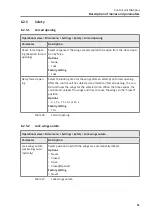
Page 41: ...variant is automatically selected Page 19 chapter 3 4 2 and Page 21 chapter 3 4 3 Factory setting Variant 1 Delay permanent open You use this parameter to specify whether and after what time the perm...

Page 42: ...y Table 18 Operating mode 6 2 2 Validations Operational view Main menu Settings Validations Parameter Description Hold open Time Change Set the hold open time The hold open time is started by an openi...

Page 43: ...ng 1 s Close delay set Shows the set close delay Close delay Remaining time Shows the remaining close delay Left direction 1 Shows the remaining validations in direction 1 Left direction 2 Shows the r...

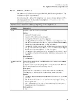
Page 44: ...g speed Select the speed for opening the wings Options Slower Slow Medium Fast Faster Factory setting Fast Closing speed Select the speed for closing the wings IMPORTANT The closing speed for unauthor...

Page 45: ...eams is ena bled Activated X The test of the safety light barriers safety PE beams is dis abled Factory setting Inactive Impact response Open Select the response for obstacle detection during the open...

Page 46: ...sed via the Impact response Close parameters of the Intrusion Wrong direction and Tailgating menus Page 48 chapter 6 2 4 3 up to Page 50 chapter 6 2 4 5 Options None The control unit attempts to conti...

Page 47: ...to be entered depend on the installed blocking element The values to be entered are on a label that is attached to the blocking ele ment Adjust values for safe operation 1 Select the Low energy menu...

Page 48: ...ged values in the Low energy menu Options No action Adopt values Status Shows whether the new values are correct or incorrect Readback 1 Shows the current settings for the values S and T for Wing 1 Re...

Page 49: ...D2 Example Contr D1 Free D2 If a validation is pending in direction 1 and a person enters the pedestrian gate in direction 2 this is an unauthorised access attempt of the type Wrong direction If you s...

Page 50: ...haviour of the wings in case of an unauthorised access attempt of the Tailgating type If you select the Activated X option the wings will not be closed in the event of an unauthorised access attempt o...

Page 51: ...t on forced opening After the control unit has detected an attempt on forced opening the con trol unit locks the wings for the selected time When the time expires the control unit unlocks the wings an...

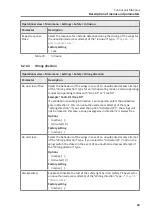
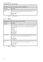
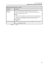
Page 52: ...s to 60 s 0 s The output Warning light barriers PE beams is not set Factory setting 0 s Table 28 Warning light barriers PE beams 6 2 6 Signalling 6 2 6 1 Buzzer Operational view Main menu Settings Sig...

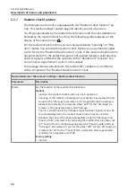
Page 53: ...no validations are pending and no free passage in that direction is possible As soon as a validation is pending or the direction is permanently free the GED turns green Standby green The GED is green...

Page 54: ...ds 5 Hz Factory setting Variant 2 On intrusion Select the display pattern for the On intrusion event Options Page 55 section Display pattern on the GED Factory setting Pulse red 2 5 Hz On wrong direct...

Page 55: ...z GED flashes in red with a frequency of 5 Hz Pulse green 5 Hz GED flashes in green with a frequency of 5 Hz Double pulse short red GED flashes in red twice every second with a pulse of 100 ms Double...

Page 56: ...ndom hit validation is confirmed with a 0 V pulse at the Random check function input Operational view Main menu Settings Random check function Parameter Description Mode Set the function of the random...

Page 57: ...justed Setting range 10 to 10000 Factory setting 1000 Count of hits Set the number of hits to be generated in the set Count of hits IMPORTANT The value for the Count of hits parameter can be a maximum...

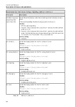
Page 58: ...nction 6 2 8 Home offset This menu is available only for pedestrian gates with swing wings Operational view Main menu Settings Home offset Parameter Description All wings You can correct or teach in t...

Page 59: ...2 1 In direction 1 Operational view Main menu Information People counter In direction 1 Parameter Description Passages total Shows the number of all validated and non validated passages in direction 1...

Page 60: ...tion type in direction 1 Tailgating Shows the number of unauthorized access attempts of the Tailgating type in direction 2 Table 36 People counter In direction 2 6 4 3 Light barriers PE beams Operati...

Page 61: ...nnected via LAN Internet access is available All IP settings are configured correctly Via Magnetic you can purchase additional hardware to connect the control unit to the Internet without connecting i...

Page 62: ...ngs All settings in the IP Settings menu are restored to de fault settings To factory setting The stored parameters in the memory area Factory settings are adopted as operating settings To FW defaults...

Page 63: ...her call the operational view or switch the voltage supply on or off Options Inactive You can change the main menu without entering a password Active You can change the main menu only after entering a...

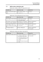
Page 64: ...bleshooting can cause severe injuries Observe possible movements of the blocking element Defec tive control may lead to inadvertent movement of the blocking element In case of damaged components take...

Page 65: ...espond ing error message is displayed Depending on error message check components wiring etc MHTM FlowMotion service expert Power supply is present Con trol unit display does not light up Control unit...

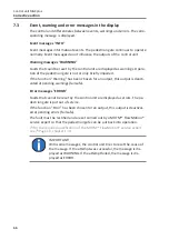
Page 66: ...en for an output this output is deacti vated at pending warnings fail safe Error messages ERROR Faults that cannot be reset by the control unit are displayed as errors The pe destrian gate is put out...

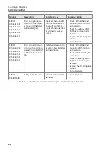
Page 67: ...otor address setting or defective mo tor electronics Check for correct motor address setting Check the CAN bus wiring Check the settings of the terminating resistance Contact service ERROR 0x3001F003...

Page 68: ...terminating re sistance Replace the IM16 input ex tension Contact service ERROR 0x50nn3048 0x50nn3049 0x50nn304A 0x50nn304B 0x50nn304C Error during communi cation with an IM16 in put extension install...

Page 69: ...the two middle operating buttons on the control unit display for 5 s Using the parameter Reboot menu path Operational view Main menu System Reboot Set the input with the Reset function NOTICE Fast re...

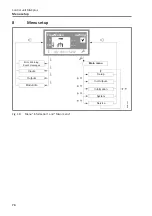
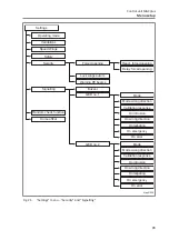
Page 70: ...us Menu setup 8 Menu setup Mag01022 10 FlowMotion mWing 1 192 168 115 242 System Service Main menu Setup Error Warning Event messages Inputs Modul info Outputs In Outputs Information Fig 18 Menu Infor...

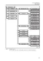
Page 71: ...tion Direction Safety Security Opening speed Closing speed Speed on fraud Signalling Home offset Control variant Delay permanent open Emergency options Hold open time Close delay Left direction 1 Left...

Page 72: ...Close General Low engery Intrusion Wrong direction Tailgating New value S New value T New value C Adopt new values Status Readback 1 Readback 2 Do not close if free Do not close Disable safety Impact...

Page 73: ...Warning PE beams Mode Mode wrong direction Validation response On intrusion On wrong direction On tailgating On emergency On error Mode Mode wrong direction Validation response On intrusion On wrong...

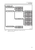
Page 74: ...puts 1 4 Relay outputs 1 6 Operating mode People counter System Reboot Language IP settings Remote support USB drive CAN bus Restore settings Service Cycle counters Operating time Date Time Main menu...

Page 75: ...Warning People counter Light barriers PE beams In direction 1 In direction 2 Passages total Valid passages Reverted Intrusion Wrong direction Tailgating Passages total Valid passages Reverted Intrusi...

Page 76: ...76 Control unit MGCplus...

Page 77: ...Direction 58 Direction 1 See Passage direction 1 Direction 2 See Passage direction 2 Disable safety 45 Intrusion 48 Tailgating 50 Wrong direction 49 Display contrast 38 Display control unit 35 Symbol...

Page 78: ...nergy 47 M Magnetic MHTM FlowMotion service expert 10 Main menu password 63 Malfunctions Control unit 67 Pedestrian gate 65 Do not close Intrusion 48 Tailgating 50 Wrong direction 49 Do not close if f...

Page 79: ...2 12 Signalling 52 Speed on fraud 44 Speed Wings 44 Status Low energy 48 Manual validation D1 43 Manual validation D2 44 Max direction 1 43 Max direction 2 43 Menu Information 40 Settings 41 Menu set...

Page 80: ...sage In direction 1 59 In direction 2 60 Val pers 9 Val pers passed 9 27 Val pers passed D1 27 Val pers passed D2 27 Val pers present 27 Val pers present D1 27 Val pers present D2 27 W Wait for homing...

Page 81: ...81 Control unit MGCplus...

Page 82: ...82 Control unit MGCplus...

Page 83: ...83 Control unit MGCplus...

Page 84: ...TIC AUTOCONTROL GMBH Grienmatt 20 D 79650 Schopfheim Germany Phone 49 7622 695 5 Fax 49 7622 695 802 info magnetic germany com www magnetic access com Sales partner Doc ID 5817 0033EN Version 00 F1004...

Reviews: