background image

27

mTripod

Receipt of goods, transport and storage

5.4 

Storage

Store packages or the product under the following conditions: 

 ›

Store the delivery in its original packaging. Observe the symbols on the 

packaging.

 ›

Do not store outdoors.

 ›

Store dry and dust free. 

 ›

Do not expose to aggressive media. 

 ›

Protect against solar irradiation.

 ›

Avoid mechanical vibrations.

 ›

Storage temperature range: –30 to +55 °C 

 ›

Relative humidity: max. 95 %, non-condensing 

Check the general condition of all components and packaging regularly, if they 

are stored for longer periods than 3 months.

Summary of Contents for MHTM FlowMotion mTripod

Page 1: ...Operating Instructions Turnstile MHTM FlowMotion mTripod Doc ID 5817 0026EN Version 02 58170026EN_02 indd 1 04 04 2019 16 08 57...

Page 2: ...2 mTripod MAGNETIC AUTOCONTROL GMBH Grienmatt 20 D 79650 Schopfheim Germany Phone 49 7622 695 5 Fax 49 7622 695 802 info magnetic germany com www magnetic access com...

Page 3: ...3 Target groups 11 2 3 1 Operator and his responsibilities 11 2 3 2 Personnel activities and qualifications 12 2 4 Personal protective equipment 13 2 5 Symbols on the device 14 2 6 For your safety 15...

Page 4: ...dation 33 7 4 2 Requirements empty conduits 33 7 4 3 Setting up foundation and placing empty conduits 34 7 4 4 Foundation and empty conduit plan and reinforcement mTripod FMTP ML 35 7 4 5 Foundation a...

Page 5: ...utting the pedestrian gate into operation 69 9 3 Switching the pedestrian gate on and off 69 9 4 Parameterising the pedestrian gate 71 10 Test book 71 11 Operation 72 12 Cleaning and maintenance 72 12...

Page 6: ...6 mTripod...

Page 7: ...e separate document Description of MGC control unit for mTripod Doc ID 5817 0025 1 2 Read and store the operating instructions Pre requisite for safe working is the observance of all specified safety...

Page 8: ...ty product 1 4 Symbols and illustrations used in these operating instructions 1 4 1 Warning notes and notes Warning notes are characterised by pictograms in these operating instructions A warning note...

Page 9: ...or injuries if it is not avoided NOTICE The signal word NOTICE points to a potentially harmful situation which leads to property damage if it is not avoided Notes and recommendations IMPORTANT The sig...

Page 10: ...e range indicated on the type plate Misapplications Any other or further use is considered improper use Magnetic is not liable for any resulting personal injury or damage to property For example the f...

Page 11: ...tions to any new provisions standards and usage conditions where required clearly regulate the responsibilities for all work on the product and with the product such as installation commissioning oper...

Page 12: ...necessary regulations Can assess the work assigned to her him recognises possible dangers and take suitable safety measures Technician Has completed training as a plant mechanic plant fitter assembly...

Page 13: ...faults X X Repairing X X Decommissioning X X Disassemble X X Dispose X 1 According to the supplied test book MHTM FlowMotion mTripod Table 2 Activities and qualifications 2 4 Personal protective equip...

Page 14: ...s hazardous areas with dangerous electrical voltage Non observance of the warning signs causes severe injuries or death The work to be carried out may only be carried out by a qualified electrician or...

Page 15: ...devices that are prescribed by national regulations such as e g residual current circuit breakers These protective devices must be provided by the customer Observe the information on the type plate C...

Page 16: ...r disposal Improper disposal can lead to damage to the environment Dispose of product in accordance with local and national laws and regulations Sort resources and supply them to recycling 2 8 Emergen...

Page 17: ...Technical data 3 1 Dimensions and design 3 1 1 mTripod ML 5 5 A A Mag00811 1300 1239 5 290 1050 882 90 180 180 110 38 515 A 100 44 60 80 Fig 1 Dimensions FMTP ML dimensions in mm A Dimensions for cust...

Page 18: ...x 1050 mm Page 17 Fig 1 Passage width 515 mm Weight Turnstile complete Approx 70 kg Optional foundation frame Approx 10 5 kg Material Housing mDure Optional foundation frame Stainless steel Housing c...

Page 19: ...s access control device Designation Value Dimensions length x width x height 730 mm x 290 mm x 1050 mm Page 19 Fig 2 Passage width 515 mm Weight Turnstile complete Approx 56 kg Optional foundation fra...

Page 20: ...20 mTripod Technical data 3 2 Clearances and line configuration to be maintained Mag00817a 1 1 50 1050 882 515 290 50 Fig 3 Clearances and line configuration to be maintained 1 Minimum distance 50 mm...

Page 21: ...0 V AC 2 1 A Max power 174 W Duty cycle 100 Table 5 Electrical connection 3 4 Operating conditions Designation Value Operating temperature range 30 to 55 C Storage temperature range 30 to 55 C Relativ...

Page 22: ...voltage 24 10 V DC Input current 10 mA per input Max cable length 1 30 m Digital outputs Number 4 open collector Input voltage 24 10 V DC Input current 100 mA Max cable length 1 30 m Relay outputs Nu...

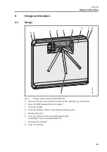
Page 23: ...or access control device provided by the customer e g card reader 2 Space for GED passage direction display 3 Control unit MGC 4 Drive for blocking element consisting of 3 blocking arms 5 Blocking arm...

Page 24: ...is option when an emergency is triggered or in the event of a power failure the blocking arm which is at the top at this time unlocks The blocking arm turns downwards When the voltage returns the bloc...

Page 25: ...the extent of damage on the transport documents or on the delivery note of the carrier Lodge complaint IMPORTANT Lodge a complaint for each defect as soon as it is recognised Compensation claims can o...

Page 26: ...roper transport can result in damage to the product Observe the symbols on the packaging Always load transport and unload packages carefully Observe dimensions Do not remove packaging until immediatel...

Page 27: ...ve the symbols on the packaging Do not store outdoors Store dry and dust free Do not expose to aggressive media Protect against solar irradiation Avoid mechanical vibrations Storage temperature range...

Page 28: ...transport goods with two persons The individual components are packed according to the expected transport conditions Do not destroy the packaging and remove only directly before assembly The packagin...

Page 29: ...anel and trapezoidal plate Front panel Cover 3 blocking arms 1 attachment set for 3 blocking arms without drop arm option 1 attachment set for 3 blocking arms with drop arm option 4 U profiles 1 assem...

Page 30: ...AUTOCONTROL GmbH D 79650 Schopfheim 1 2 3 5 6 7 10 11 12 4 8 9 Fig 5 Type plate 1 Product name 2 Serial number 3 Power supply 4 Frequency 5 Current consumption 6 Power consumption 7 Protection class I...

Page 31: ...destrian gate to tip over causing bruising and serious injury Install the pedestrian gate on the foundation according to the description Observe and follow separate notes and instructions provided by...

Page 32: ...FURA100 FURA101 2 Attachment set BSKL100 for gluing the base plate Attachment set BSS100 for mounting the turnstile on the base plate 4 Use screws M8 x 16 from attachment set BSS100 for mounting the...

Page 33: ...must meet the following additional requirements Concrete C35 45 XD 3 XF2 Foundation depth at least 800 mm frost proof Adjust foundation depth to the local conditions Reinforcement mesh according to r...

Page 34: ...nduit plan Page 35 Fig 6 Page 36 Fig 7 2 If installed outdoors lay the reinforcement braid 3 Place empty conduits according to the foundation and empty conduit plan in the foundation hole 4 Close empt...

Page 35: ...5 100 200 200 560 560 1300 1350 400 40 80 80 117 5 117 5 10 22 5 45 8 5 1 800 180 Mag00813b Fig 6 mTripod FMTP ML foundation and empty conduit plan dimensions in mm 1 Foundation frost depth outdoor a...

Page 36: ...36 mTripod Installation and assembly A B A B Mag00814 40 40 40 40 8 280 720 80 90 280 264 1270 264 9 0 9 0 800 8 Fig 7 Reinforcement plan FMTP ML dimensions in mm...

Page 37: ...1 2 4 5 100 285 285 730 780 400 40 80 80 117 5 117 5 10 22 5 8 5 1 800 180 Mag00925 Fig 8 mTripod FMTP MS foundation and empty conduit plan dimensions in mm 1 Foundation frost depth outdoor area 2 Ou...

Page 38: ...38 mTripod Installation and assembly A B A B Mag00926 40 40 40 40 8 280 720 80 90 280 264 700 264 9 0 9 0 800 8 Fig 9 Reinforcement plan FMTP ML dimensions in mm...

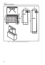
Page 39: ...se plate and drilling template mTripod FMTP ML dimensions in mm 1 Base plate FURA100 2 Feed through for empty conduits 3 Holes M8 for threaded rods or screws 14 x see item 6 and 9 4 Holes 20 mm for fo...

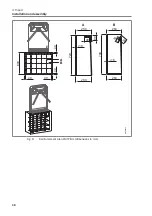
Page 40: ...3 1 2 4 5 6 7 8 Mag00936 10 669 5 120 1150 120 Fig 11 Base plate and drilling template mTripod FMTP MS dimensions in mm 1 Base plate FURA101 2 Feed through for empty conduits 3 Holes for threaded rod...

Page 41: ...8 Assembly of the mTripod 7 8 1 Mounting variant Direct mounting With this mounting variant you mount the turnstile directly on a foundation For the variant mTripod FMTP ML you need 8 foundation ancho...

Page 42: ...M 0V 0V 0V 0V 0V 24V NO4 NC4 NO5 NC5 NO6 NC6 NO1 NO2 NO3 C1 3 C4 6 1 2 3 2 3 1 4 5 4 Mag00847a Fig 12 Mounting variant Direct mounting mount turnstile shown here mTripod FMTP ML 1 Drill hole FMTP ML 8...

Page 43: ...eholes with compressed air 3 Inject composite mortar into the boreholes 4 Female threaded sleeves with internal thread to the bottom of the boreholes by hand The BSS100 mounting kit contains mounting...

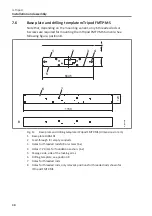
Page 44: ...shing the finished floor Prerequisites The foundation raw floor was erected The empty conduits were laid The foundation unfinished floor has hardened Base plate and drilling template Tripod FMTP ML Pa...

Page 45: ...ring the base plate 1 Foundation raw floor 2 Planned finished floor 3 Drilling template 4 Nut M8 slightly above the planned finished floor FMTP ML 8 x and FMTP MS 6 x 5 Threaded rods M8 x 210 stainles...

Page 46: ...x off threaded rods 20 mm above the finished floor Mag00929 Fig 15 Flexing off threaded rods 3 Place the turnstile on the threaded rods Page 47 Fig 16 4 Mount the turnstile with U profiles and nuts 5...

Page 47: ...1 2 3 4 5 6 7 8 X2 DO1 DO2 DO3 DO4 COM 0V 0V 0V 0V 0V 24V NO4 NC4 NO5 NC5 NO6 NC6 NO1 NO2 NO3 C1 3 C4 6 1 2 3 Mag00930 1 2 3 3 1 4 Fig 16 Mounting variant Mount base plate Mount turnstile shown here...

Page 48: ...or mTripod FMTP MS Attachment set BSKL100 for gluing the base plate Attachment set BSS100 for mounting the turnstile on the base plate foundation anchors and composite mortar are not required Prerequi...

Page 49: ...on the floor Make sure that the markings are either washable or invisible Mag00854 Fig 17 Mark outline 3 Put the base plate aside The underside must face upwards 4 Clean the floor with the HaftClean...

Page 50: ...tool When selecting the tool consider the material of the base 10 Wait for the curing time 11 Place the turnstile on the base plate Page 51 Fig 20 12 Place U profiles washers and hexagonal screws NOTI...

Page 51: ...N5 IN6 IN7 IN8 X1 1 2 3 4 5 6 7 8 X2 DO1 DO2 DO3 DO4 COM 0V 0V 0V 0V 0V 24V NO4 NC4 NO5 NC5 NO6 NC6 NO1 NO2 NO3 C1 3 C4 6 1 2 3 Mag00931 1 1 2 4 3 3 Fig 20 Mounting variant Glue base plate Mount turns...

Page 52: ...Cover front panel and blocking arms are not assembled on delivery SERVICE BAT F IN A C C E S S TO P R O G R E S S X20 DO5 OUT 0V 0V 0V EN P P E D O I X11 X10 X12 POWER E E IN1 IN2 IN3 IN4 IN5 IN6 IN7...

Page 53: ...emble the trapezoidal plate To do this loosen the 2 screws SERVICE BAT F IN A C C E S S TO P R O G R E S S X20 DO5 OUT 0V 0V 0V EN P P E D O I X11 X10 X12 POWER E E IN1 IN2 IN3 IN4 IN5 IN6 IN7 IN8 X1...

Page 54: ...front panel A click sound is heard each time it clicks into place SERVICE BAT F IN A C C E S S TO P R O G R E S S X20 DO5 OUT 0V 0V 0V EN P P E D O I X11 X10 X12 POWER E E IN1 IN2 IN3 IN4 IN5 IN6 IN7...

Page 55: ...6 NO3 C1 3 C4 6 Fig 25 Attachment of the front panel 8 Assemble the cover The cover is held by 2 magnets CAUTION Danger of crushing Hold the cover with both hands only on the side Do not hold the cove...

Page 56: ...option per pedestrian gate Assemble the blocking arms with the correct attachment set SERVICE BAT F IN A C C E S S TO P R O G R E S S X20 DO5 OUT 0V 0V 0V EN P P E D O I X11 X10 X12 POWER E E IN1 IN2...

Page 57: ...X10 X12 POWER E E IN1 IN2 IN3 IN4 IN5 IN6 IN7 IN8 X1 1 2 3 4 5 6 7 8 X2 DO1 DO2 DO3 DO4 COM 0V 0V 0V 0V 0V 24V NO4 NC4 NO5 NC5 NO6 NC6 NO1 NO2 NO3 C1 3 C4 6 1 2 3 Mag00849 3 2 1 Fig 28 Assembly of the...

Page 58: ...d by 2 magnets Disassembling the cover 1 Place the supplied tool near the magnets 2 Lever the cover forward with the tools 3 Unhook the cover SERVICE BAT F IN A C C E S S TO P R O G R E S S X20 DO5 OU...

Page 59: ...at the front or top edge 2 Tilt the cover backwards until the magnets close the cover SERVICE BAT F IN A C C E S S TO P R O G R E S S X20 DO5 OUT 0V 0V 0V EN P P E D O I X11 X10 X12 POWER E E IN1 IN2...

Page 60: ...ge 56 Fig 27 or Page 57 Fig 28 3 Loosen the 4 screws of the front panel Page 55 Fig 25 4 Disassemble front panel NOTE Front panel may break if disassembled incorrectly Alternately open side closures F...

Page 61: ...g 23 Closing the housing 1 Assemble trapezoidal plate 2 Assemble holding bracket 3 Assemble front panel 4 Assemble blocking arms 5 Assemble cover Page 41 chapter 7 8 7 12 Checking the assembly After a...

Page 62: ...s may work on the electrical system Switch off power supply and secure against re activation before performing any work Test for absence of voltage Keep moisture and dust away from live parts Penetrat...

Page 63: ...use Operation in other electro magnetic environmental conditions may cause interference or malfunctions Place control lines and mains cables into separate conduits Customer access control devices sig...

Page 64: ...the system is powered down Secure against reactivation DANGER Mortal danger by electric voltage 2 Strip mains cable and strands according to the following figure 20 8 30 8 2 3 1 Mag00810 Fig 32 Stripp...

Page 65: ...4 NC4 NO5 NC5 NO6 NC6 NO1 NO2 NO3 C1 3 C4 6 1 2 3 Mag00853a 1 2 3 4 Fig 33 Placing and connecting the mains cable 1 Feed through for empty conduits and lines 2 Straps for fixing empty conduits and lin...

Page 66: ...eleased The motor starts up briefly so that the drop arm can be released Turnstiles without drop arm option If the signal drops the passage is enabled in both directions 8 5 Installing and connecting...

Page 67: ...ch you can drill out if necessary We recommend universal screws 4 5 x 25 mm as fastening screws The maximum permitted drilling depth is 7 mm SERVICE BAT F IN A C C E S S TO P R O G R E S S X20 DO5 OUT...

Page 68: ...the specification on the type plate Are the prescribed protective devices installed Is the pedestrian gate connected according to wiring diagram Is the emergency signal transmitter correctly connected...

Page 69: ...gloves Safety shoes 9 2 Putting the pedestrian gate into operation IMPORTANT Commissioning must be carried out in accordance with the test book See separate document Test Book MHTM FlowMotion mTripod...

Page 70: ...ICE BAT F IN A C C E S S TO P R O G R E S S X20 DO5 OUT 0V 0V 0V EN P P E D O I X11 X10 X12 POWER E E IN1 IN2 IN3 IN4 IN5 IN6 IN7 IN8 X1 1 2 3 4 5 6 7 8 X2 DO1 DO2 DO3 DO4 COM 0V 0V 0V 0V 0V 24V NO4 N...

Page 71: ...sation see separate document Description of MGC control unit for mTripod Doc ID 5817 0025 10 Test book The pedestrian gate must be checked at least once a year in accordance with the test book The tes...

Page 72: ...ID 5817 0025 12 Cleaning and maintenance 12 1 Cleaning the pedestrian gate NOTICE Aggressive cleaning aids and substances Aggressive detergents and consumables may damage or destroy components electr...

Page 73: ...k the housing for damage from the outside Operator Every 6 months Check the attachment of the blocking arms Technician Check function of the external residual current operated device Technician Every...

Page 74: ...ress can be found on your delivery receipt invoice or the rear of these operating instructions Spare part lists can be obtained on request 15 Customer service Our customer service can be contacted for...

Page 75: ...tion Page 69 chapter 9 3 16 1 Safety during decommissioning Qualification of personnel Technician Magnetic MHTM FlowMotion service expert Page 12 chapter 2 3 2 Personal protective equipment Wear the f...

Page 76: ...wing personal protective equipment Work clothes Protective gloves Safety shoes 17 2 Dismantling and disposing of the pedestrian gate Prerequisites The pedestrian gate is not in operation Page 75 chapt...

Page 77: ...6 2 2005 AC 2005 Electromagnetic compatibility EMC Part 6 2 Generic standard Immunity for industrial environments EN 61000 6 3 2007 A1 2011 AC 2012 Electromagnetic compatibility EMC Part 6 3 Generic...

Page 78: ...78 mTripod...

Page 79: ...FMTP ML 35 mTripod FMTP MS 37 Line configuration 20 M Magnetic MHTM FlowMotion service expert 12 Mains cable Connecting 64 Maintenance schedule 73 Index A Access control devices Assembly 66 Connecting...

Page 80: ...ase plate 48 Mounting the base plate 44 N Notices Presentation 8 O Operating conditions 21 Operation 72 Operator Responsibility 11 P Parameterise 71 Personal protective equipment 13 Personnel Qualific...

Page 81: ...81 mTripod...

Page 82: ...82 mTripod...

Page 83: ...83 mTripod...

Page 84: ...Grienmatt 20 D 79650 Schopfheim Germany Phone 49 7622 695 5 Fax 49 7622 695 802 info magnetic germany com www magnetic access com Sales partner Doc ID 5817 0026EN Version 02 F10044441 58170026EN_02 in...

Reviews: