background image

50

mWing

Installation and assembly

1.  Place and align base plate.

NOTICE

Wrong orientation of the pedestrian gate! The pedestrian gate is not sym-

metrically constructed. Align the pedestrian gate so that the passage side 

is on the correct side. Note figure base plate.

2.  Draw the outline of the base plate on the floor. Make sure that the mark-

ings are either washable or invisible.

3.  Put the base plate aside. The underside must face upwards.
4.  Clean the floor with the "HaftClean" surface cleaner.
5.  Clean the underside of the base plate with the surface cleaner "HaftClean 

Metall".

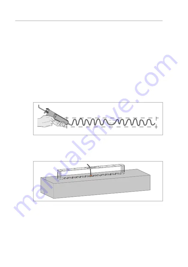
6.  Apply construction adhesive "Klebt + D Dicht Power" to the floor in the 

form of a beat within the marking. Apply less construction adhesive to-

wards the edge.

Mag00855

Fig. 20:  Apply construction adhesive

7.  Immediately place the base plate on the construction adhesive. Observe 

markings.

M

ag0093

3

Fig. 21:  Place base plate

8.  Press the base plate on well immediately. If the base plate stands out due 

to unevenness of the floor, weight the base plate.

Summary of Contents for MHTM FlowMotion mWing

Page 1: ...Operating Instructions Pedestrian gate with swing doors MHTM FlowMotion mWing Doc ID 58170034EN Version 00 mWing mWing mWing...

Page 2: ...2 mWing MAGNETIC AUTOCONTROL GMBH Grienmatt 20 D 79650 Schopfheim Germany Phone 49 7622 695 5 Fax 49 7622 695 802 info magnetic germany com www magnetic access com...

Page 3: ...Operator and his responsibilities 11 2 3 2 Personnel activities and qualifications 12 2 4 Personal protective equipment 13 2 5 Symbols on the device 14 2 6 For your safety 14 2 7 To protect the envir...

Page 4: ...ments foundation 35 7 4 2 Requirements empty conduits 35 7 4 3 Setting up foundation and placing empty conduits 36 7 4 4 Foundation and empty conduit plan and reinforcement 37 7 5 Base plate and drill...

Page 5: ...on and off 65 9 4 Parameterising the pedestrian gate 67 10 Test book 67 11 Operation 68 12 Cleaning and maintenance 69 12 1 Cleaning the pedestrian gate 69 12 2 Maintenance schedule 69 13 Corrective...

Page 6: ...6 mWing...

Page 7: ...see separate document Description of MGC control unit for mWing Doc ID 5817 0033 1 2 Read and store the operating instructions Pre requisite for safe working is the observance of all specified safety...

Page 8: ...oduct 1 4 Symbols and illustrations used in these operating instructions 1 4 1 Warning notices and notices Warning notes are characterised by pictograms in these operating instructions A warning note...

Page 9: ...r injuries if it is not avoided NOTICE The signal word NOTICE points to a potentially harmful situation which leads to property damage if it is not avoided Notes and recommendations IMPORTANT The sign...

Page 10: ...rature range indi cated on the type plate Misapplications Any other or further use is considered improper use Magnetic is not liable for any resulting personal injury or damage to property For example...

Page 11: ...tions to any new provisions standards and usage conditions where required clearly regulate the responsibilities for all work on the product and with the product such as installation commissioning oper...

Page 12: ...necessary regulations Can assess the work assigned to her him recognises possible dangers and take suitable safety measures Technician Has completed training as a plant mechanic plant fitter assembly...

Page 13: ...aults X X Repairing X X Decommissioning X X Disassemble X X Dispose X 1 According to the supplied test book MHTM FlowMotion mWing Table 2 Activities and qualifications 2 4 Personal protective equipmen...

Page 14: ...f power supply and secure against re activation be fore performing any work Test for absence of voltage Perform electrical installation in accordance with the applica ble regulations Install protectiv...

Page 15: ...disposal Improper disposal can lead to damage to the environment Dispose of product in accordance with local and national laws and regulations Sort resources and supply them to recycling 2 8 Emergenc...

Page 16: ...1 mWing Mag01000 1300 1239 5 X 360 X 50 180 293 888 1050 A A A 100 44 60 80 Fig 1 Dimensions of the mWing sizes in mm X corresponds to the ordered passage width A Installation space for reader without...

Page 17: ...riants 520 mm or 960 mm Weight Pedestrian gate Approx 82 kg Optional foundation frame Approx 10 6 kg Material Housing mDure Optional foundation frame Stainless steel Table 3 Dimensions and design mWin...

Page 18: ...0 V AC 2 1 A Max performance 174 W Duty cycle 100 Table 4 Electrical connection 3 4 Operating conditions Designation Value Operating temperature range 30 to 55 C Storage temperature range 30 to 55 C R...

Page 19: ...voltage 24 10 V DC Input current 10 mA per input Max cable length 1 30 m Digital outputs Number 4 open collector Input voltage 24 10 V DC Input current 100 mA Max cable length 1 30 m Relay outputs Nu...

Page 20: ...3 5 4 6 2 2 1 Fig 3 Setup here showing mWing 1 Room for access control device provided by the customer e g card reader 2 Space for GED passage direction display 3 Swing door e g glass wing 4 Inlay 5...

Page 21: ...s 1 A module Slave function no control unit 2 C module Master function the control unit is located on the master side 3 B module Slave and master function the control unit is located on the master sid...

Page 22: ...22 mWing Design and function 4 2 1 A module Mag01003 Fig 5 A module shown without cover here the A module performs the slave function...

Page 23: ...23 mWing Design and function 4 2 2 B module Mag01004 Fig 6 B module shown without cover here The B module performs the master function...

Page 24: ...24 mWing Design and function 4 2 3 C module Mag010005 Fig 7 C module shown without cover here The C module performs the master and slave functions...

Page 25: ...oors are closed The swing doors only open after authorisation from an external command unit such as a card reader Attempted cheating such as passage in the wrong direction or a second person following...

Page 26: ...he extent of damage on the transport documents or on the delivery note of the carrier Lodge complaint IMPORTANT Lodge a complaint for each defect as soon as it is recognised Compensation claims can on...

Page 27: ...oper transport can result in damage to the product Observe the symbols on the packaging Always load transport and unload packages carefully Observe dimensions Do not remove packaging until immediately...

Page 28: ...e the symbols on the packaging Do not store outdoors Store dry and dust free Do not expose to aggressive media Protect against solar irradiation Avoid mechanical vibrations Storage temperature range 3...

Page 29: ...transport goods with two persons The individual components are packed according to the expected transport conditions Do not destroy the packaging and remove only directly before assembly The packaging...

Page 30: ...e parts not installed 2 covers not installed 2 strips not installed 1 assembly tool 1 drilling template Documentation Electrical circuit diagram test book these operating in structions and description...

Page 31: ...ble in different heights All figures show the swing doors in the standard height Swing doors in the standard height are installed for delivery Higher swing doors are delivered separately 1 2 3 Mag0100...

Page 32: ...Q Ser Nr Made in Germany MAGNETIC AUTOCONTROL GmbH D 79650 Schopfheim 1 2 3 5 6 7 10 11 12 4 8 9 Fig 10 Type plate 1 Product name 2 Serial number 3 Power supply 4 Frequency 5 Current consumption 6 Not...

Page 33: ...strian gate to tip over causing bruising and serious injury Install the pedestrian gate on the foundation according to the description Observe and follow separate notices and instructions provided by...

Page 34: ...he base plate Base plate FURA100 Attachment set BSKL100 for gluing the base plate Attachment set BSS100 for mounting the pedestrian gate on the base plate 1 Use screws M8 x 16 from at tachment set BSS...

Page 35: ...t the following additional re quirements Concrete C35 45 XD 3 XF2 Foundation depth at least 800 mm frost proof Adapt foundation depth to the local conditions Reinforcement mesh according to reinforcem...

Page 36: ...and empty con duit plan 2 If installed outdoors lay the reinforcement braid 3 Place empty conduits according to the foundation and empty conduit plan in the foundation hole 4 Close empty conduit to pr...

Page 37: ...01011 90 90 120 100 100 130 35 60 115 Master Paid Unpaid Slave 1 800 Fig 11 Foundation and empty conduit plan dimensions in mm 1 Foundation frost depth outdoor area 2 Outline mWing 3 Feed through for...

Page 38: ...38 mWing Installation and assembly A B A B Mag01012 40 40 40 40 8 280 720 80 90 280 264 1270 264 9 0 9 0 800 8 Fig 12 Reinforcement plan dimensions in mm...

Page 39: ...on and assembly 120 x 80 180 600 180 900 180 780 1080 1300 685 Mag01013 Master Paid Unpaid Slave Master Slave 180 1 5 3 4 4 3 3 5 4 6 6 120 x 80 120 x 80 7 8 9 2 Fig 13 Foundation and empty conduit pl...

Page 40: ...ection 2 from Unpaid to Paid 3 Empty conduit for external data line 4 Empty conduit for 230 V 5 Minimal diameter 40 mm empty conduit for supply data and signal lines 6 Optional for empty conduit for 2...

Page 41: ...0 2 Feed through for empty conduits 3 Bores M8 for threaded rods or screws see positions 6 and 9 4 Bores 20 mm for foundation anchors 5 Passage side 6 Base plate FURA100 only relevant positions for th...

Page 42: ...alls tile joints and railings using a laser or scale 7 7 Mounting the mWing 7 7 1 Mounting variant Direct mounting With this mounting variant you mount the pedestrian gate directly on a foun dation Re...

Page 43: ...pedestrian gate 1 Boreholes 8 x 2 Sleeve with inner thread 12 x 90 M8 stainless steel 8 x 3 Washer A 8 4 mm stainless steel 4 x 4 Screw M8 x 30 stainless steel IMPORTANT Follow the separate notices an...

Page 44: ...with inner thread to the bottom of the boreholes by hand The BSS100 attachment set contains mounting aids 5 Wait for the curing time Follow separate instructions 6 Place pedestrian gate 7 Place sleeve...

Page 45: ...floor Prerequisites The foundation raw floor was erected The empty conduits were laid The foundation unfinished floor has hardened Base plate and drilling template Page 41 Fig 14 1 Mount the base pla...

Page 46: ...7 6 5 Mag10010 Fig 16 Mounting and preparing the base plate 1 Foundation raw floor 2 Planned finished floor 3 Drilling template 4 Nut M8 slightly above the planned finished floor 5 Threaded rods M8 x...

Page 47: ...d nuts 2 Flex off threaded rods 20 mm above the finished floor Mag10012 Fig 18 Flexing off threaded rods 3 Place the pedestrian gate on the threaded rods Page 48 Fig 19 4 Mount the pedestrian gate wit...

Page 48: ...stallation and assembly 3 Mag10013 8x 1 2 Fig 19 Mounting version base plate mounting Mounting the pedestrian gate 1 Nut M8 8 x 2 Washer A 8 4 mm stainless steel 4 x 3 Threaded rods M8 x 210 stainless...

Page 49: ...for gluing the base plate Attachment set BSS100 for mounting the pedestrian gate on the base plate foundation anchors and composite mortar are not required Prerequisites The foundation finished floor...

Page 50: ...he underside must face upwards 4 Clean the floor with the HaftClean surface cleaner 5 Clean the underside of the base plate with the surface cleaner HaftClean Metall 6 Apply construction adhesive Kleb...

Page 51: ...curing time 11 Place the pedestrian gate on the base plate Page 52 Fig 22 12 Place washers and hexagonal screws NOTICE Possible damage to the finished floor Use screws M8 x 16 from attachment set BSS...

Page 52: ...g Installation and assembly Mag10027 8x 1 2 3 Fig 22 Mounting version gluing plate mounting Mounting the pedestrian gate 1 Screw M8 x 16 stainless steel 8 x 2 Washer A 8 4 mm stainless steel 4 x 3 Bas...

Page 53: ...mounted on the floor Covers side parts and lower strips are not assembled on delivery The swing doors are available in different heights Swing doors in the standard height are installed for delivery H...

Page 54: ...54 mWing Installation and assembly 1 Arrange electrical connections Page 59 chapter 8 2 Mount the strips Mag10018 1 2 3 4 Fig 24 Mounting the strips 1 Screw 2 Washer 3 Strip 4 Thread...

Page 55: ...e side parts click Mag10017 Mag10019 Fig 25 Assembly of the side part 4 Assemble cover The cover is held on by magnets CAUTION Danger of crushing Hold the cover with both hands only on the side Do not...

Page 56: ...in different heights All figures show the swing doors in the standard height Swing doors in the standard height are installed for delivery Higher swing doors are delivered separately Mag01009 1 2 3 4...

Page 57: ...are needed for parameterisation 3 Place the glass wings before the attachment points 4 Screw on the glass wings at the top and bottom 7 10 Dismounting and mounting the cover For the following activit...

Page 58: ...hands only on the side Do not hold the cover at the top or bottom edge 2 Tilt the cover backwards until the magnets close the cover Mag10030 Fig 29 Assembly of the cover 7 11 Checking the assembly Aft...

Page 59: ...may work on the electrical system Switch off power supply and secure against re activation be fore performing any work Test for absence of voltage Keep moisture and dust away from live parts Penetrati...

Page 60: ...use Operation in other electro magnetic environmental conditions may cause interference or malfunc tions Place control lines and mains cables into separate conduits Customer access control devices sig...

Page 61: ...he system is powered down Secure against reactivation DANGER Mortal danger by electric voltage 3 Strip mains cable and strands according to the following figure 20 8 30 8 2 3 1 Mag00810 Fig 30 Strippi...

Page 62: ...nd connecting the mains cable 1 Terminals 2 Mains cable to be connected 8 4 Connecting customer control lines IMPORTANT For connecting the control lines provided by the customer see separate document...

Page 63: ...resent at this input the pedestrian gate is in operation 8 5 Installing and connecting customer access control devices You can install access control devices in the following locations At both ends of...

Page 64: ...cification on the type plate Are the prescribed protective devices installed Is the pedestrian gate connected according to electrical circuit diagram Is the emergency signal transmitter correctly conn...

Page 65: ...ve gloves Safety shoes 9 2 Putting the pedestrian gate into operation IMPORTANT Commissioning must be carried out in accordance with the test book See separate document Test Book mWing Doc ID 5837 001...

Page 66: ...sioning 1 Install cover Page 57 chapter 7 10 2 Switch the pedestrian gate on or off using the on off switch Mag01010 1 Fig 33 Switching the mWing on and off 1 On and off switch 3 Assemble cover Page 5...

Page 67: ...w unexpected behaviour Only Magnetic MHTM FlowMotion service experts must set parameters IMPORTANT For parameterisation see separate document Description of MGC control unit for mWing Doc ID 5817 0033...

Page 68: ...nal transmitters and signal receivers as well as on the parameterisa tion of the control unit We recommend to create a description for the operation depending on the connected devices and the paramete...

Page 69: ...th a mild household cleaner 4 Carefully clean areas with persistent dirt with spirit 5 Dry surfaces with a dry cloth 12 2 Maintenance schedule The maintenance plan lists all work required to ensure sa...

Page 70: ...Spare parts are available from your authorised dealer The address can be found on your delivery receipt invoice or the rear of these operating instruc tions Spare part lists can be obtained on reques...

Page 71: ...Page 65 chapter 9 3 16 1 Safety during decommissioning Qualification of personnel Technician Magnetic MHTM FlowMotion service expert Page 12 chapter 2 3 2 Personal protective equipment Wear the follo...

Page 72: ...owing personal protective equipment Work clothes Protective gloves Safety shoes 17 2 Dismantling and disposing of the pedestrian gate Prerequisites The pedestrian gate is out of order Page 71 chapter...

Page 73: ...tibility EMC Part 6 2 Generic standard Immunity for industrial environments EN 61000 6 3 2007 A1 2011 AC 2012 Electromagnetic compatibility EMC Part 6 3 Generic standard Emission standard for resident...

Page 74: ...74 mWing...

Page 75: ...tor Responsibility 11 P Parameterise 67 Personal protective equipment 13 Personnel Qualification 12 Index A Access control devices Assembly 63 Connecting 63 Assembly 33 42 Cover 58 mWing 53 Testing 58...

Page 76: ...pair 70 S Safety 10 Safety guards Install 60 Scope of delivery 30 Spare parts 70 Storage 28 Switching off 65 Switching on 65 T Target groups 11 Technical data 16 Test book 67 Transport 27 Type plate 3...

Page 77: ...77 mWing...

Page 78: ...78 mWing...

Page 79: ...79 mWing...

Page 80: ...ETIC AUTOCONTROL GMBH Grienmatt 20 D 79650 Schopfheim Germany Phone 49 7622 695 5 Fax 49 7622 695 802 info magnetic germany com www magnetic access com Sales partner Doc ID 58170034EN Version 00 F1004...

Reviews: