10
MGC control unit
Digital inputs, digital outputs and relay outputs
2.2
Digital outputs and relay outputs
ä
For the definition "Entry" and "Exit" see Page 40, chapter 5.1.
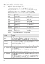
By parameterising the outputs, you assign certain functions to the outputs.
If the function is marked with "|", the output is inverted (Fail Safe).
The following functions are assigned to the outputs as default settings.
Clamp
Description
Function
DO1
Digital output 1
GED red entry
DO2
Digital output 2
GED green entry
DO3
Digital output 3
GED red exit
DO4
Digital output 4
GED green exit
NO1
Relay output 1
Passage pulse entry
NO2
Relay output 2
Passage pulse exit
NO3
Relay output 3
–
NO4/NC4
Relay output 4
Passage free entry
NO5/NC6
Relay output 5
Passage free exit
NO6/NC6
Relay output 6
Random hit
Table 5:
Factory settings Digital outputs and Relay outputs
Function
Function
–
Outputs that you assign this function "–" to are deactivated.
| Error
When the control unit recognises any safety-relevant error or error, the
output with this function is deactivated (Fail safe).
ä
| Warning
When the control unit recognises any Warning, the output with this function
is deactivated (Fail safe).
ä
Gate ready
Pedestrian gate is ready for operation
This output is activated as soon and as long as the pedestrian gate is ready
for operation.
Passage pulse entry Counting pulse for the passage from the zone not controlled (ZNC) to the
zone controlled (ZC)
When the next end position is reached in the zone controlled direction, a
counting pulse (300 ms) is emitted via this output. A counting pulse is also
emitted in the "Permanent open" operating mode.
Passage pulse exit
Counting pulse for the passage from the zone controlled (ZC) to the zone not
controlled (ZNC)
When the next end position is reached in the zone not controlled direction, a
counting pulse (300 ms) is emitted via this output. A counting pulse is also
emitted in the "Permanent open" operating mode.

