11
MGC control unit
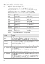
Digital inputs, digital outputs and relay outputs
Function
Function
Passage free entry
Control of display "Passage in zone controlled direction cleared"
When the passage in the zone controlled direction is cleared, a permanent
signal is emitted via this exit. This exit may also be used to block a pulse
encoder such as a card reader for the opposite direction. The request
generator must be equipped with a lock input for this.
Passage free exit
Control of display "Passage in zone not controlled direction cleared"
When the passage in the zone not controlled direction is cleared, a
permanent signal is emitted via this output. This exit may also be used to
block a pulse encoder such as a card reader for the opposite direction. The
request generator must be equipped with a lock input for this.
Buzzer/Siren (alarm) Acoustic signal transmitter
This output is used to connect a signal transmitter.
Random hit
Hits of the random function, signal transmitter
The random function generated a hit. You can connect a signal lamp or a
siren to this output, for example.
The passage remains blocked until the random hit / validation is confirmed
with a 0 V pulse at the "random function" input.
Service mode active Pedestrian gate in service mode
As soon as the service mode is switched on via the slider on the control unit
MGC, this output is activated.
GED red entry
Gate End Display connection
Connect the GED "red" of the zone not controlled to this output.
GED green entry
Gate End Display connection
Connect the GED "green" of the zone not controlled to this output.
GED red exit
Gate End Display connection
Connect the GED "red" of the zone controlled to this output.
GED green exit
Gate End Display connection
Connect the GED "green" of the zone controlled to this output.
Magnet RL1 (internal
use)
Connection magnet RL1
Magnet RL1 for locking is connected to this exit by default. The magnet locks
in passage direction left.
Magnet RL2 (internal
use)
Connection magnet RL2
Magnet RL2 for locking is connected to this exit by default. The magnet locks
in passage direction right.
Table 6:
Function digital outputs and relay outputs

