4
45-610 Displacer Type Liquid Level Switches and Proof-er
®
Switches
1
5
2
3
4
3
2
1
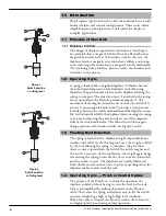
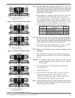
Figure 1
Switch position
on rising level
1
5
2
3
4
3
2
1
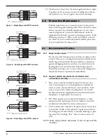
Figure 2
Switch position
on falling level
1.0 Introduction
Displacement type level switches offer the industrial user a wide
choice of alarm and control configurations. These units utilize
simple buoyancy principle and are well suited for simple or
complex applications.
1.1
Principle of Operation
1.1.1 Displacer Controls
The design of displacer operated level switches is based upon
the principle that a magnetic field will not be affected by non-
magnetic materials such as 316 stainless steel. In this case, the
displacer moves a magnetic attraction sleeve within a non-mag-
netic enclosing tube and actuates a magnetic switch mechanism.
The enclosing tube provides a pressure seal to the chamber and,
therefore, to the process.
1.2
Operating Cycle
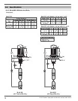
A spring is loaded with a weighted displacer
➀
which is heavier
than the liquid. Immersion of the displacers caused by rising
liquid level imparts buoyancy forces on the displacer allowing the
spring to compress. The attraction sleeve
➁
attached to the spring,
moves upward into the field of a permanent magnet
➂
. The
movement of the magnet toward the sleeve causes the switch
➃
to
actuate. A non-magnetic barrier tube
➄
provides a static pressure
boundary between the switch mechanism and the displacer assem-
bly. As the liquid level falls, the displacer lowers, causing the spring
to extend, and moving the attraction sleeve out of the magnetic
field of the switch mechanism. This allows the switch to again
change position and to break or make. See Figures 1 and 2.
1.3
Floating Roof Detection
The spring is loaded with a displacer weight suspended from a
stainless steel cable. As the floating roof rises, the weight is lifted
by the roof allowing the spring to compress, the attraction
sleeve to move upward into the field of the switch magnet and
the switch to actuate. As the roof lowers, the weight again hangs
free causing the spring to extend, the sleeve to move downward
and the switch to reset. The displacers are usually fabricated
from ductile metals, such as brass, to prevent sparking when the
displacer makes contact with the roof.
1.4
Operating Cycle — Proof-er Control Option
The purpose of the Proof-er is to check the operation of a
displacer control without having to raise the level in the tank.
This is accomplished by pulling downward on the Proof-er
cable. This causes the spring loaded lever arm to lift the switch
actuator, simulating a high or high–high level condition.
When the cable is released, the Proof-er returns the actuator to
its original position resuming normal operation.


