3
46-620 B73 & Series 75 Liquid Level Switche
s
3. Tighten set screw(s) at base of switch housing.
4. Unscrew and remove switch housing cover. The threads
have been lubricated to facilitate removal.
NOTE: For supply connections, use wire with a minimum rating of
+167° F (+75° C) as required by process conditions. Use a
minimum of 14 AWG wire for power and ground field wires.
NOTE: Housing must be grounded via protective ground screw in the
base of the housing.
NOTE: On high temperature applications (above +250° F [+121° C] in
float chamber), high temperature wire should be used
between control and first junction box located in a cooler area.
On non-hazardous applications, flexible conduit may be used
between the control and the first junction box.
5. The switch terminals are located next to the conduit
outlet to facilitate wiring. Bring supply wires through
conduit outlet. Route extra wire around enclosing tube
under the baffle plate, and connect them to the proper
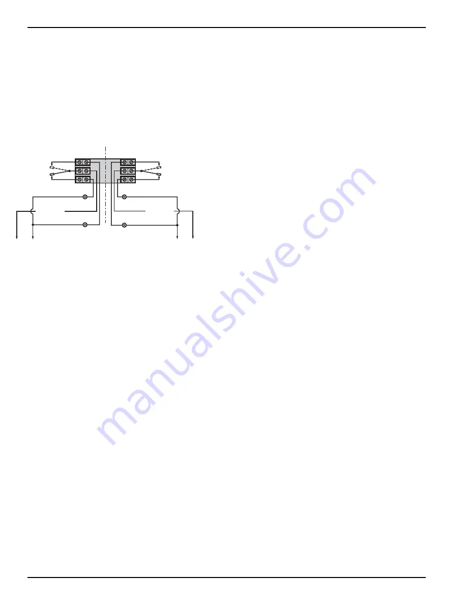
terminals. Refer to the wiring diagram,
Figure 3
, or your
switch bulletin for this information.
NOTE: For models with Series HS or H1 switches with high tempera-
ture lead wire, the leads are routed out through the conduit
opening by the factory. A suitable conduit box should be
provided for the connection of the leads to the control wiring.
6. Dress wiring to ensure no interference or contact with tilt
of switch or replacement of switch housing cover.
Caution:
Observe all applicable electrical codes and proper wiring
procedures.
Caution:
In hazardous areas, do not power the unit until the conduit
is sealed and the enclosure cover is screwed down
securely.
7. Replace housing cover.
8. If control has been furnished with an explosion proof or
moisture proof (gasketed) switch housing, it must be
sealed at the conduit outlet with a suitable compound or
non-hardening sealant to prevent entrance of air.
9. Test switch action by varying liquid level in float chamber.
NOTE: If switch mechanism fails to function properly, check vertical
alignment of control housing and consult installation bulletin
for additional wiring information on switch mechanism
furnished. See
Section 6.1.2, Switch and Housing
Reference
on page 19.
10. Check cover to base fit to be certain gasketed joint is tight.
A positive seal is necessary to prevent infiltration of mois-
ture laden air or corrosive gasses into switch housings.
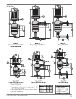
Internal Circuit
(Right) Switch
1
2
3
Load
Load
Close on high level
Close on low level
Line
4
5
6
Internal Circuit
(Left) Switch
Load
Load
Close on high level
Close on low level
Line
Common
Common
Figure 3
Wiring Diagram


