5
46-620 B73 & Series 75 Liquid Level Switche
s
2.4
Switch Differential Adjustment
The standard differential of Series 75 float models with
one switch may be field adjusted. Adjustment may be
necessary if a wider differential needs to be set to overcome
switch chatter caused by the process.
NOTE: This procedure may be applied to single switch models only.
The differential, or the amount of level travel between
switch-on and switch-off, may be adjusted by repositioning
the lower jam nuts on the float stem. This adjustment is
different for high level and low level controls. Refer to the
appropriate section below for adjustment instructions.
NOTE: Maximum differential adjustment is 1 inch.
Caution:
Differential adjustments should NOT be made in the field
on tandem float models. Switch actuation levels have
been set at the factory to meet customer specifications.
Variations in actual conditions from design conditions,
usually require special control modifications. Consult the
factory or your local representative for assistance.
2.4.1 Low Level Controls
On low level controls the switch trips on the lower
actuation point and resets on the higher actuation point.
Widening the differential will allow the switch to trip
on the original actuation point and reset at a later or
higher point.
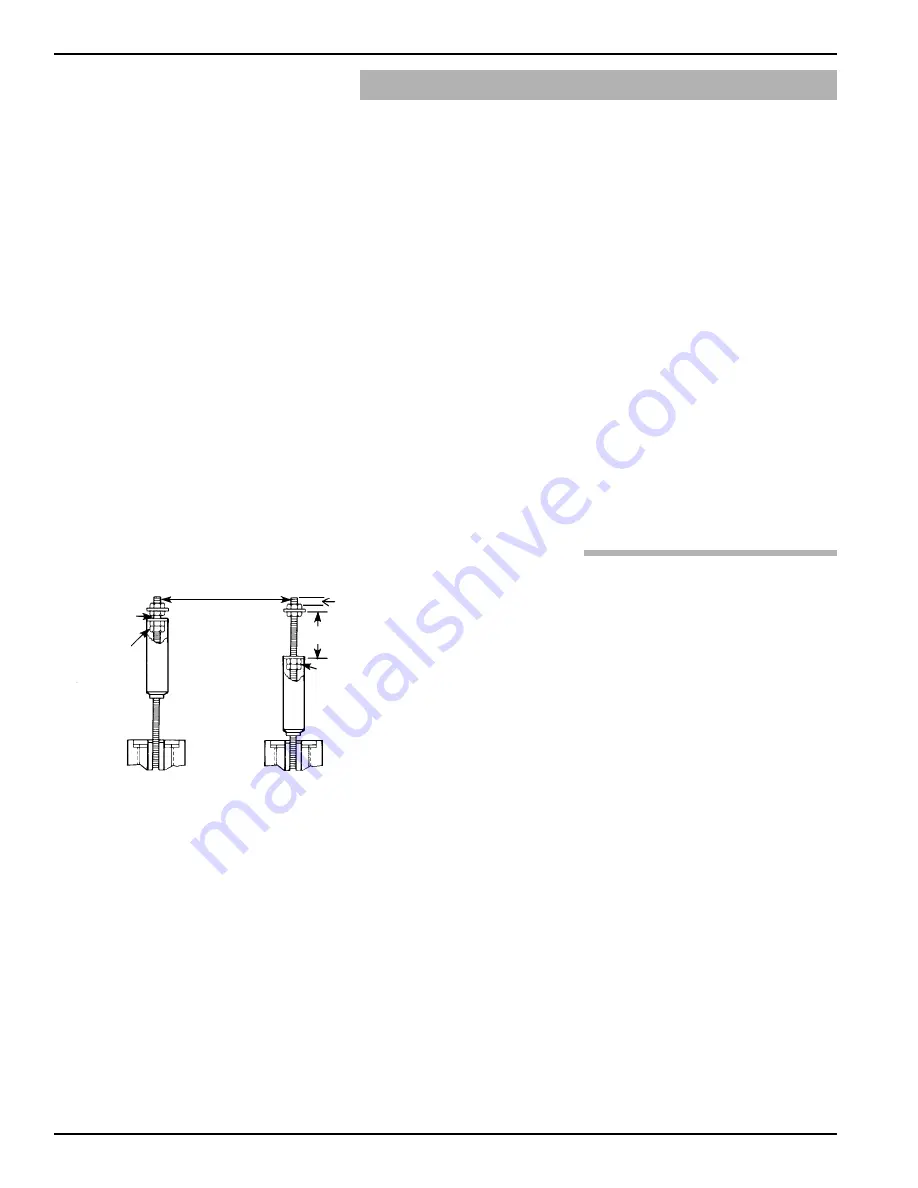
The differential on low level controls may be adjusted by
repositioning the lower jam nuts on the float stem. The
standard factory setting is for a minimum amount of play
(gap) between the top jam nuts and the attraction sleeve.
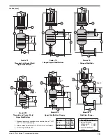
Refer to
Figure 6
.
1. Determine what change in differential is necessary.
NOTE: To widen the differential by one inch, the lower jam nuts must
be set proportionately lower on the stem (i.e., in this example
by 1 inch).
2. Make sure power source is turned off.
3. Unscrew and remove switch housing cover.
4. Disconnect power supply wires from switch mechanism.
Pull wires out of conduit connection opening in housing
base. Refer to
Figure 8
.
5a. Perform system shut-down procedures as required to
relieve pressure from float chamber of control. Allow unit
to cool.
Figure 6
Figure 7
Slight play (gap)
Must be allowed
(0.03" typical)
Replace in same position
Position of bottom
jam nuts (normal
factory setting)
Maximum gap setting
(applies to models
having a single
switch mechanism
with a single magnet
actuator only)
Drop bottom
jam nuts to
increase gap
setting (refer
to above
instructions)
1.00 (25 mm)
D


