3
INST
ALLATION
INSTALLATION LOCATION
Kotron transmitters should be located for easy access for
service, calibration and monitoring. Transmitters should not
be exposed to ambient temperatures below -40°C (-40°F) or
above +70°C (+160°F).
Special precaution should be made to prevent exposure
to corrosive atmosphere, excessive vibration, shock or
physical damage.
It is common practice to use the metal tank wall as the
reference electrode (refer to Operating Principle).
In such cases, it is required that the probe housing makes a
good electrical connection to the tank wall. If there is any
doubt about this connection due to the use of PTFE thread
tape, gaskets, paint, rust, or any other reason, a separate
strap should be installed between the probe housing and
the tank.
CAUTION:
This unit contains CMOS electronics
which may be damaged by static electricity. Do not
touch any semi-conductor devices unless you are
properly grounded.
MET
AL WALLED TANKS
On water based liquids, there should be no problem with
sensitivity or linearity. With non-conductive, low dielectric
media, sensitivity can be enhanced by locating the
probe close to and parallel with the tank wall. If this is
not practical, a concentric ground tube, sometimes called
a stilling well, may be a solution.
NOTE
: These comments are true for glass-lined metal
walled
tanks also.
T
anks/Silos –
with non-conductive materials of construction
W
ith plastic, concrete, wood, or any other non-conductive
walled vessels, the reference electrode mentioned in the
“Operating Principle” section on page 1 needs clarification.
Most commonly, this electrode will be in the form of a
concentric ground tube (i.e. stilling well). Refer to
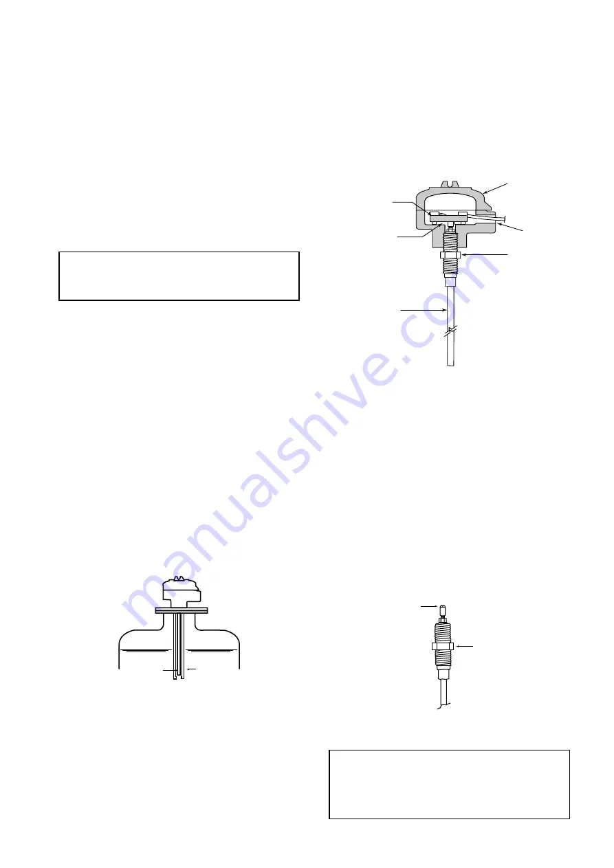
Figure 1.
In questionable circumstances, consult the Factory
. In all
cases, a good electrical connection must be made between
the ground surface and the probe housing.
MOUNTING
T
wo-wire transmitters with probes up to and including
305 mm (12") in length are shipped pre-assembled. Two-
wire transmitters with probes over 305 mm (12") in length
are shipped unassembled to avoid damage during transit.
They must be assembled before mounting. Follow the
mounting procedure for your particular case.
MOUNTING PROCEDURE A
Pre-assembled transmitters,
integral mount with rigid probe
1.
Thread transmitter assembly into mounting bushing on
tank.
2. Tighten securely, being certain that the wrench is applied
ONL
Y
to the packing gland nut. See
Figure 2
.
3. Proceed to Wiring instructions
on page 5.
MOUNTING PROCEDURE B
Unassembled transmitters,
integral mount with rigid probe
1.
Thread probe into mounting bushing on tank.
2. Tighten securely, being certain that the wrench is
applied
ONL
Y
to the packing gland nut. See
Figure 3
.
3. Screw the transmitter/probe housing onto the probe.
See
Figure 3
. Do not pinch or cut the packing gland.
4. Screw housing on probe until hand tight. Housing can be
wrench tightened to align electrical connection. See
Figure 2
.
5. Remove housing cover.
6. Locate the white wire, which is fastened to the (+) Probe
Terminal. Connect the free end of this wire to the probe
connection screw.
7. Proceed to the "WIRING INSTRUCTIONS" on page 5.
CAUTION:
Packing glands used on all Magnetrol
rigid probe assemblies have been sealed at the
factory under controlled conditions. Care must be
exercised when installing probe assemblies to
avoid breaking pressure tight gland seal, which
destroys the seal.
;
;
;;
Figure 1
Figure 2
Integral mount models with rigid probe
Figure 3 –
Threaded probe
Probe connection screw
Packing gland nut
(when installing, use wrench
on this nut only)
Probe
Concentric
ground tube
Probe
terminal
PC board
Packing
gland nut
Transmitter
housing
Electrical
entry
Rigid probe


