6
CALIBRA
TION
AUXILIARY CURRENT METER
In order to calibrate the transmitter
, you may use either the
loop current meter, or a second current meter which has an
internal resistance of less than 10 Ω.
It should read currents in the range of 1 to 25 mA, with a
resolution of 0.01 mA. Using a meter of less resolution will
somewhat reduce the calibration accuracy.
An error of 0.2 mA is equivalent to a 1% error, based on the
full scale current of 20 mA.
To calibrate the instrument:
1. Remove transmitter housing cover.
2. Check that the LED is glowing (shadowing the LED by
hand may be helpful in brightly lit environments).
NOTE
: The LED will glow brighter with increasing signal.
a. If the LED is lit, continue to step 3.
b. If the LED isn’t lit, check for supply voltage of 14 to
40 V at the terminal strip. Also confirm that the
polarity is correct. If LED still does not light, replace
the cover and contact factory.
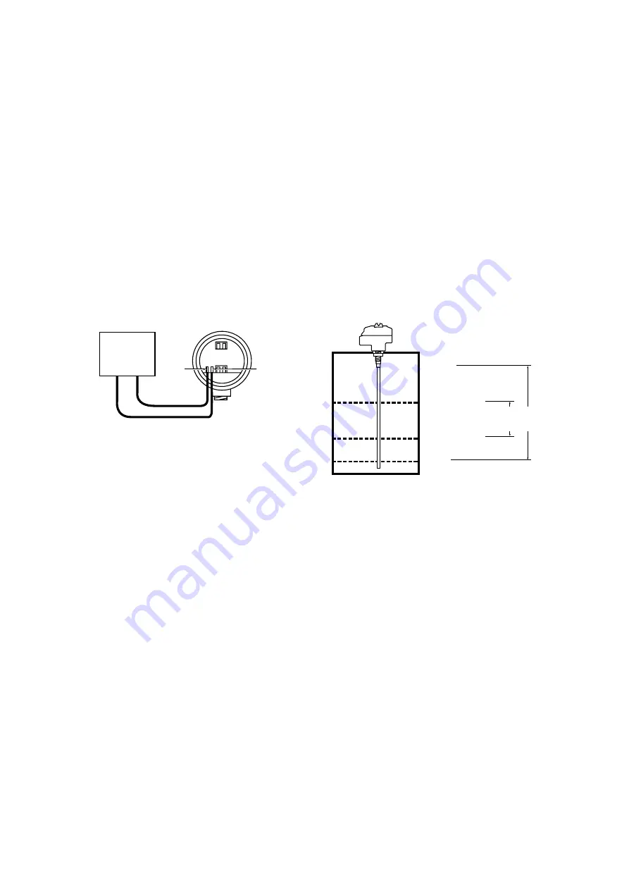
3. Connect the auxiliary meter’s positive lead to Test point
1 and its negative lead to Test point 2. See
Figure 7
.
NOTE
: This use of TP- and TP+ allows the loop current to
be monitored at the location where the adjustments are
being made, without removing any wires.
It is not necessary to use this auxiliary meter if another
means is available to measure loop current.
a. If the LED goes completely out, proceed to step 4.
b. If the LED doesn’t go out, check the following:
• the meter is properly connected.
• the appropriate meter range has been selected.
• meter resistance is less than 10 Ω for the
selected range.
4. The loop current should now be in the range of 1.5 mA
to 38 mA, which is normal at this point.
TWO POINT CALIBRA
TION - LEVEL INCREASE
T
wo calibration procedures are described on page 7. Follow
the one which fits your application.
Please note the following definitions used in the calibration
procedures, referring to
Figure 8
.
L0 =
the level of material in the vessel which corresponds
to 4.0 mA of loop current, i.e., the 0% level.
L1 =
a material level higher than L0.
L2 =
a material level higher than L1, but less than L3.
L3 =
the level of material in the vessel which corresponds
to 20.0 mA of loop current, i.e., the 100% level.
NOTE
: T
o avoid the possibility of a “dead zone”, L0 must
be at least 50 mm (2") above the end of the probe for
conductive media and 100 mm (4") above for non-
conductive media.
Calibration A = when material in tank can be set to L0 (0%)
and L3 (100%).
Calibration B = when material in tank can be set to L1
(greater than 0%) and L2 (less than 100%).
NOTE
: Calibration Procedure A gives the most accurate
results and is the recommended procedure in all cases.
+
TP +
-
TP -
B
A
Figure 8
Figure 7
Auxiliary
current
meter
L3 - 100 %
L2 - less than 100 %
L1 - greater than 0 %
L0 - 0 %
Calibration
procedure


