O P E R A T I O N A L C O N S I D E R A T I O N S
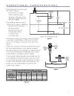
Sensor
Reference
Point
(NPT)
Sensor
Reference
Point
(BSP)
Sensor
Reference
Point
(Flange)
2" (50 mm)
Figure 5
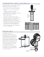
3
Tank
Height
Sensor Reference Point
Safety
Zone
Bottom Blocking Distance
Measurement
Region
Sensor
Level
Distance
Level = Tank Height – Distance
Level Trim
Distance = Sensor Level Distance - Level Trim
Top Blocking
Distance
Figure 4
Radar applications are characterized by
three basic conditions:
•
Dielectric (process medium)
•
Distance (measuring range)
•
Disturbances (turbulence, foam,
false targets, multiple reflections
and rate of change)
The PULSAR R96 Radar transmitter is
offered with four antenna configurations:
•
Polypropylene Dielectric Rod
•
TFE Dielectric Rod
•
All-Plastic Dielectric Rod:
Polypropylene or Halar
®
•
4" (100 mm) Horn
•
6" (150 mm) Horn
Maximum measuring range (distance) is measured from the
sensor reference point (bottom of NPT thread, top of BSP
thread, or face of flange) to the bottom of the tank. Refer to
Figure 4.
Ideally, the 6" (150 mm) horn antenna should be used to ensure
the best possible performance in all operational conditions.
Since that is impractical, other antennas are available. The chart
below shows the maximum measuring range of each antenna
based on dielectric and turbulence. Refer to Figure 5.
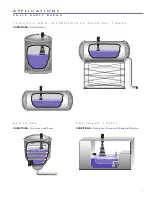
Noise and media buildup drastically decrease reliable measure-
ment. Although it is theoretically possible to measure a liquid
level on the antenna, liquid should not be allowed closer than
2 inches (50 mm) from the bottom of the antenna due to the
decrease in accuracy when liquid level is present on the
antenna. Refer to Figure 6.
R96 Maximum Recommended Measuring Range in feet (meters)
Turbulence None or Light
Turbulence Medium or Heavy
Dielectric >
1.7 - 3
3 - 10
10 - 100
1.7 - 3
3 - 10
10 - 100
Antenna Type
Dielectric Rod
16 (5)
39 (12)
66 (20)
10 (3)
29 (9)
39 (12)
4" Horn
6" Horn
33 (10)
82 (25
131 (40)
16 (5)
39 (12)
52 (16)
Figure 6


