20
58-601 Pulsar
®
Radar Transmitter
2.6.5 Menu: Step-By-Step Procedure
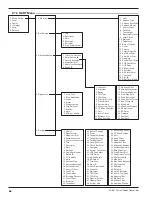
The following table provides a complete explanation of the
software menus displayed by the Radar transmitter. Use this
table as a step-by-step guide to configure the transmitter.
The first column presents the menus shown on the trans-
mitter display. The displays are in the order they would
appear if the arrow keys were used to scroll through the
menu. The numbers are not shown on the display. They
are provided as a reference.
The second column provides the actions to take when
configuring the transmitter. Additional information or an
explanation of an action is given in the third column.
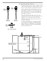
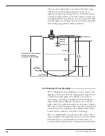
The following drawings are provided as reference for the
configuration procedure.
Use of the included PACT
ware
™
PC program is highly
recommended and invaluable for troubleshooting and
advanced calibration. A HART RS232 or USB modem
(purchased separately) is required. See MAGNETROL
PACT
ware
™
bulletin 59-101.
Tank
Height
Sensor Tank Height =
Distance from process
connection to tank bottom
20 mA
4 mA
Sensor Reference Point
Sensor Offset (+)
Blocking
Distance
Distance
Safety Zone
Media
Level
Level Offset
Lowest
Measurable
Value
Sensor
Reference
Point
Sensor
Reference
Point
Sensor
Reference
Point
NPT Process
Connection
BSP Process
Connection
ANSI or DIN Flange (Welded)


