21
58-601 Pulsar
®
Radar Transmitter
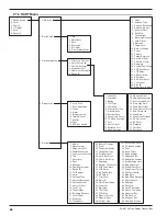
2.6.5.1 Radar Transmitter Menu Table
Note: Press UP arrow 3 times to reach screen where menu language can be chosen.
Display
Action
Comment
1
*Level*
*Quality*
*%Output*
*Loop*
Transmitter Display
Transmitter default display.
Level
,
Signal Quality
,
%Output
,
and
Loop
values cycle every 5 seconds. All screens
(except 2–6) default to this screen after 5 minutes of no
keystrokes or if a Fault or Warning message is displayed.
2
Level
xxx.x units
Transmitter Display
Transmitter displays
Level
measurement in chosen unit of
measure.
3
Distance
xxx.x units
Transmitter Display
Transmitter displays
Distance
measurement in chosen unit
of measure. Measurement includes
Sensor Offset
value.
Transmitter reports Distance regardless of Blocking
Distance and Level Offset settings.
4
Qual xx
xxx.x units
Transmitter Display
Transmitter display showing
Level
and
Quality
of signal
reflection. Good values are 20–90
5
%Output
xx.x%
Transmitter Display
Transmitter displays
%Output
measurement derived from
20 mA span.
6
Loop
xx.xx mA
Transmitter Display
Transmitter displays
Loop
value (mA).
7
Units
(select)
Select
units of measure
Select
cm
(xxxx),
inches
(xxx.x),
meters
(xx.xx) or
feet
(xx.xx). Allowable decimal position is controlled; four char-
acters is maximum reading. Decimal position is controlled
by
Units
and
Tank Height
.
8
AntnaTyp
(select)
Select
the
Antenna Type
used.
Select first 7 digits of the Model Number (first 4 are signifi-
cant). Information is located on the nameplate mounted
on the side of transmitter housing.
9
AntnaExt
(select)
Select
the
Antenna Extension
used.
Select last 3 digits of the Model Number corresponding to
the Antenna Extension. This relates to the maximum nozzle
length where it can be used:
0**
≤
1" (25 mm), -1**
≤
4" (100 mm), -2**
≤
8" (200 mm),
-3**
≤
12" (300 mm)
10
AntnaMnt
(select)
Select
the type of
Antenna Mounting
Select
NPT
,
BSP
, or
Flange
11
SnsrOfst
xx.x units
Enter
the
Sensor Offset
value.
Sensor Offset
is the distance (+ or -) from the Sensor ref-
erence point (bottom of NPT thread or flange face, top of
BSP thread) to the top of the tank.
12
Tank Top
(select)
Select
the shape/type of tank top
Select the metallic tank top structure:
Flat
,
Horizontal
Cylinder
,
Dome
,
Irregular
, or
Other (non-metallic)
.
13
Tank Ht
xxx.x units
Enter
the
Tank Height
Tank Height
is measurement from the bottom to the top
of tank.
14
Block Dis
xxx.x units
Enter
the
Blocking Distance
Blocking Distance
defines an area near the antenna where
reflections can not be measured effectively due to antenna
ringing. It is measured from the
Sensor Reference
point.
Minimum value is set by choice of Antenna Type and is
calculated as antenna 2" (50 mm); larger values are
encouraged. Output will be held at value corresponding to
Blocking Distance
. Do not allow liquid on to the antenna.
15
LevlOfst
xxx.x units
Enter
the
Level Offset
Level Offset
defines an area at the bottom of the vessel
where reflections can not be measured effectively due to
angled bottoms, heating coils, reflections from flat metal
tank bottom in low dielectric applications, etc. It is the
distance from the bottom of the tank to the lowest valid
level reading. Level reading will never be lower than
Level Offset
value.


