5
58-601 Pulsar
®
Radar Transmitter
1.1.2 Configuration Information
Some key information is needed to configure the PULSAR
radar transmitter. Complete the following operating param-
eters table before beginning configuration.
NOTE: The transmitter will already be configured if this information was
provided with the order.
Display
Question
Answer
Units
What units of measurement will be
used?
_____________
Antenna
What type of antenna is being used?
Type
Select first 7 digits of Model number.
(See nameplate on side of antenna)
_____________
Antenna
What is maximum nozzle length that
Extension
the antenna can be used?
Select last 3 digits of Model number.
(See nameplate on side of antenna)
_____________
Antenna
Is the antenna mounting NPT, BSP,
Mount
or flanged?
_____________
Sensor
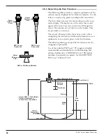
What is the distance from the top (100%)
Offset
of the tank and the Sensor Reference
point (bottom of NPT thread, top of BSP
thread, or face of flange?)
_____________
Tank Top
Is the Tank Top Flat, Horizontal Cylinder,
Dome, Irregular or other (non-metallic)?
_____________
Tank
What is the tank height?
_____________
Height
NOTE:
Sensor Tank Height =
Distance from process
connection to tank bottom
Blocking
What is the distance from Sensor
Reference point to Maximum Level?
Maximum level should never be less
than 2" (50 mm) from bottom of antenna. _____________
Level
Is there a region at the very bottom of the
Offset
vessel that cannot be measured due to
heating coils, angle tank bottom, etc.?
_____________
Dielectric
What is the dielectric of the process
medium?
_____________
Turbulence Is turbulence a consideration?
_____________
Rate of
What is the maximum rate the level
Change
will rise or fall?
_____________
Foam
Will there be foam on the surface?
_____________
Set
What is the 0% reference point for the
4.0 mA
4.0 mA value?
_____________
Set
What is the 100% reference point for
20.0 mA
the 20.0 mA value?
_____________


