15
50-605 Kotron RF Point Model 80/81 Level Switches
3.0
Reference Information
3.1
Troubleshooting
3.1.1 Probe
Caution:
When an insulated probe is used in a hazardous and/or
abrasive medium, the probe should be inspected annual-
ly for any nicks, cuts or abrasions which may ruin the
integrity of the insulation. In the event that wear is found,
replace the probe or consult the factory for further instruc-
tions. This procedure is critical in vessels containing
hazardous media.
To check for malfunctioning sensing probe:
1. Remove the white probe lead form the sensing probe and
isolate it from ground.
2. Connect an ohmmeter between the sensing probe terminal
and ground. (stainless steel probe nut or housing base).
3. Measure the resistance between the probe and the stainless
steel probe nut, or probe electronic housing with an
ohmmeter. (Select the highest resistance scale available).
If the resistance measures infinity, the probe is operating
correctly. If the resistance measures less than infinity, there
may be a problem with the probe. Call the factory for
additional assistance.
4. Inspect a malfunctioning probe for a cut in the insulating
sheath or looseness in the seal at the probe mounting nut.
If neither is apparent, check for heavy conductive buildup
between probe and mounting nut.
NOTE: When performing checks 3 and 4 in conductive media, take
resistance reading when medium is at maximum level.
5. If probe test is working properly, check for insufficient
ground, loose or broken wiring, including white probe
wire. Also check continuity between probe mounting nut
and metal tank — there should be continuity (zero resist-
ance). If there is resistance, check for excessive Teflon tape
used on probe threads.
3.1.2 Electronics
Refer to the following procedure to test the pre-amplifier
P.C. boards, the amplifier and the shielded twisted cable
between the probe and the amplifier.
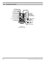
NOTE: Refer to Figure 14 on page 21 for location of potentiometer.


