50-605 Kotron RF Point Model 80/81 Level Switches
16
Caution:
This procedure changes any previous calibration of the
amplifier. If the unit checks out as operational, it will have
to be recalibrated before being used in the process.
3.1.2.1 Narrow differential point units
1. Turn off the power to the unit.
2. Remove the leadwire from the probe.
3. Turn the setpoint potentiometers fully counterclockwise.
4. Turn all time delay potentiometers fully counterclockwise.
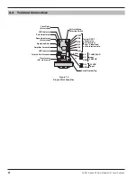
5. Move the probe level range jumper to the HI position.
Refer to Figure 9 on page 9.
a. When the probe range jumper (switch) is in the HI
position, a low level is simulated. When it is in the LO
position, a high level is simulated.
b. On remote mounted units, this jumper is located inside
the probe housing on the probe preamplifier board.
6. Turn on power to the unit.
7. The red LEDs will be off. Adjust the narrow differential
point potentiometer(s) counterclockwise until the LED(s)
turn on. Then slowly adjust each potentiometer clockwise
until the LED turns off.
8. The probe range jumper (switch) can now be switched
between the HI and LO positions and the LEDs will go
on and off. The relays will also go on and off accordingly.
If your unit operates as described above, the probe pream-
plifier board, the probe preamplifier cable and amplifier
are functioning correctly.
If your unit does
NOT
operate as described above, it is
malfunctioning. Perform the following checks:
1. Take DC voltage reading across probe preamplifier
terminals – should be approximately 12 VDC.
2. Take AC voltage reading across probe preamplifier
terminals – should be .1 to .2 VAC.
3. Consult factory – have test data available for discussion.
NOTE: These values can also be taken at probe preamplifier
wiring terminals on remote installations.


