background image

Kotron

®  

Sentinel 

Models 822, 832 and 842

Software Ver. 2.0D Integral Mount
Software Ver. 2.0C Remote Mount

Installation and Operating Manual

RF

Capacitance

Point

Level

Switches

Summary of Contents for STI Kotron 822

Page 1: ...Kotron Sentinel Models 822 832 and 842 Software Ver 2 0D Integral Mount Software Ver 2 0C Remote Mount Installation and Operating Manual RF Capacitance Point Level Switches ...

Page 2: ...procedures when working with electrostatic sensitive components WARNING Explosion hazard Do not connect or disconnect equipment unless power has been switched off or the area is known to be non hazardous Low Voltage Directive For use in Category II installations If equipment is used in a manner not specified by manufacturer protection provided by equipment may be impaired Notice of Trademark Copyr...

Page 3: ...rator Set Up 10 2 2 Program Paths 11 2 3 Calibration Single Point 12 2 3 1 Program Path 1 Configuration 12 2 3 2 Program Path 2 Single Point 13 2 4 Calibration Multi Point 16 2 4 1 Program Path 1 Configuration 16 2 4 2 Program Path 3 Probe Calibration 17 2 4 2 1 Probe Calibration Tips 18 2 4 2 2 Error Messages in PRLO HI Menus 19 2 4 3 Program Path 4 Multi Point 20 2 4 4 Program Path 5 Service 22 ...

Page 4: ... the model and serial numbers for future reference when ordering parts 1 2 Electrostatic Discharge ESD Handling Procedure Magnetrol s electronic instruments are manufactured to the highest quality standards These instruments use electronic components that may be damaged by static electricity pre sent in most work environments The following steps are recommended to reduce the risk of component fail...

Page 5: ...observed See Section 1 7 Wiring 1 3 2 Equipment and Tools No special equipment or tools are required to install the Model 822 832 or 842 switch The following items are recommended 11 8 open end wrench or adjustable wrench to fit the probe process connection size and type Flat blade screwdriver 1 3 3 Operational Considerations The Model 822 832 or 842 switch should be located for easy access for se...

Page 6: ...erly grounded Caution When a probe is used in an abrasive medium inspect the probe periodically for visible surface wear If damage to the probe insulation is found replace the probe Metal Walled Tanks On water based liquids there should be no problem with sensitivity or linearity With non conductive low dielectric media sensitivity can be enhanced by locating the probe close to and parallel with t...

Page 7: ...ment must be located outside of the nozzle Do not horizontally mount the unit in a nozzle deeper than 3 inches 75 mm Refer to Figure 5 The medium may buildup in the nozzle and cause false activation Alternate Horizontal Mounting On applications involving viscous liquids or materials which tend to cling or buildup horizontally mounted probes should be installed at a slight downward angle to allow m...

Page 8: ...wrench is applied ONLY to the mounting gland Refer to Figure 9 3 Screw the amplifier housing onto the probe Refer to Figure 9 4 Screw housing on the probe until hand tight Housing can be wrench tightened to align conduit connection with conduit 5 Locate the white wire which is fastened to the probe terminal P Connect the free end of this wire to the probe connection screw 6 Proceed to Section 1 7 ...

Page 9: ...s cable up through the packing gland nut until the cable is taut Tighten the packing gland nut 8 Cut the cable 1 35 34 mm above the packing gland nut and strip off 1 25 32 mm of insulation 9 Slide the Teflon retaining bushing onto the cable and seat it into the packing gland nut Slide the clamp onto the cable and seat it against the Teflon retaining bushing 10 Tighten both socket head screws on th...

Page 10: ...e attach the red wire from the probe to the connection on preamplifier see Figure 12 1 6 3 Remote Wiring Connections To connect preamplifier to amplifier use shielded twisted pair 22 gauge stranded connectors part number 09 7146 001 1 Strip approximately 0 4 inch 10 mm of outer jacket insu lation from each end of the shielded twisted pair 2 At the probe preamplifier end cut the bare shield wire of...

Page 11: ...NC contacts if the normally closed NC contacts are used NOTE If the snubbers are not wired properly in parallel with the relay contacts external electrical noise may disturb the operation of the instrument Refer to Section 1 7 3 Relay Wiring Chart for different relay wiring options Refer to Figure 13 for terminal locations NOTES 1 Relay 2 and relay 3 can be utilized for lead lag pump sequenc ing m...

Page 12: ...gher setting of a wide differential point 4 LLFS low level fail safe means a material level in the tank which is equal to or below a The setting of a narrow differential point b The lower setting of a wide differential point 5 a When the relay coil is de energized a connection is made between terminals C common and NC nor mally closed and there is no connection between C and NO normally open b Whe...

Page 13: ...UN mode UP RAISE Use to scroll up through menu selections or raise numeric values There are three speeds for scrolling numeric values Ramp speed is increased by continuously depressing the UP arrow key To decrease speed as the desired value is approached release the UP arrow key and unit will revert to the slowest ramp speed DOWN LOWER Use to scroll down through menu selec tions or lower numeric v...

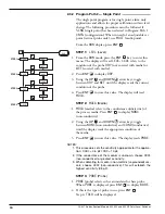
Page 14: ...res Section 2 5 in conjunction with the standard calibration procedures 2 2 Program Paths In order to properly calibrate the Sentinel the Calibration instructions are broken down into the five PATHS described below Access to program paths is granted with the following key strokes Configuration Press ENT and UP arrow keys simultaneously Single Point Press ENT Probe Calibration Press UP and DOWN arr...

Page 15: ...ENT and the UP arrow key simultaneously to enter the menu The display will read CNFG Configuration is the first mode in configuring the Sentinel Refer to the previous NOTE 2 Press ENT to confirm configuration selection and unit will display COMM COMM Communications refers to a future RS 485 option of the Sentinel Although selections appear in the flowchart screened area and in the software program...

Page 16: ... Press ENT to store this value The display will read MDIA STEP 2 MDIA Media 1 MDIA media refers to the conductance n dielectric of the process media Press ENT to display NONC non conductive 2 Using the UP and DOWN arrow keys toggle between NONC non conductive and COND conductive until the display reads the appropriate condition of the media 3 Press ENT to store this value The display reads PRBE NO...

Page 17: ...ime Delay High 1 TDHI time delay high selects the desired setting of time delay on rising level When TDHI is displayed press ENT to display current value 2 Using the UP or DOWN arrow keys scroll up or down to achieve the desired numeric value of the time delay high Time delay is adjustable between 0 and 90 seconds one second is recommended 3 When the appropriate value is displayed press ENT to sto...

Page 18: ...ying any or all of the preceding values CAL will lock in all the values and store them in memory Press ENT to display NO do not calibrate 2 Press ENT if it is desired to leave current values 3 If new values are desired use the UP and DOWN arrow keys to toggle to YES calibrate 4 Press ENT to lock all the new values in memory and return to the RUN mode NOTE Ensure that the level of the process media...

Page 19: ... will read CNFG Configuration is the first mode in configuring the Sentinel Refer to the NOTE above 2 Press ENT to confirm configuration selection and unit will display COMM COMM Communications refers to a future RS 485 option of the Sentinel Although selections appear in the flowchart screened area of diagram at left and in the software program these features are not avail able at this time 3 Wit...

Page 20: ...is menu from the RUN mode press the UP and DOWN arrow keys simultaneously The display will read REVW review 2 Press ENT to display PRLO probe low 3 Press ENT to display the previously stored PRLO point 4 Press ENT to display PRHI 5 Press ENT to display the previously stored PRHI point 6 Press ENT to display PRLO 7 Press the DOWN arrow to return to the main path The display will read CAL NOTE If re...

Page 21: ...ress the UP arrow key to leave the CAL mode and return to the RUN mode MAGNETROL INTL M M M Probe calibration is complete Proceed to Section 2 4 3 Program Path 4 Multi Point 2 4 2 1 Probe Calibration Tips If you mistakenly get into the wrong area of the program for instance PRLO data when PRHI data was intended remember pressing all the three tactile feedback keys ENT UP DOWN arrows simultaneously...

Page 22: ...entry when displayed value underflows 0 or during PRHI when displayed value underflows 1 3 2 LO Occurs when stored PRHI measurement not display would be less than currently stored PRLO measurement In other words the capacitance being used to set the PRHI point is less than the capacitance used to set the PRLO 4 2 HI Occurs when stored PRLO measurement not display would be more than currently store...

Page 23: ...l allows for selection of normal or lead lag pump control 2 If this is the desired condition press ENT 3 The next level of the menu will be displayed the selection of normal or lead lag pump control Choosing NORM will allow normal operation of the relays If lead lag pump sequencing is desired press the DOWN arrow key to display LEAD NOTE Selection of LEAD lead lag affects relays 2 and 3 only and d...

Page 24: ... the desired setting is displayed press ENT to lock in the value and to display LVLO low trip point 5 Press ENT to display the current value 6 Use the UP or DOWN arrow key to raise or lower the value 7 When the desired setting is displayed press ENT to lock in the value and display LVHI 8 Press ENT once again to display the current value for LVHI high trip point 9 Use the UP or DOWN arrow key to r...

Page 25: ...econd NOTE Relays 2 3 and 4 are configured in the same manner as Relay 1 except that the fault condition is not an option 2 4 4 Program Path 5 Service From the RUN display press the ENT and DOWN arrow keys simultaneously The Service program path is designed to aid the customer in troubleshooting the Sentinel it should be accessed only with the assistance from Magnetrol factory personnel Only the T...

Page 26: ...T Test The test mode allows manual scrolling of the process level via the keypad and LED display This checks all relay settings artificially Press ENT to display TRIP Relays will change state trip at the calibrated points Use the UP or DOWN arrow keys to toggle to HOLD In this setting relays will not change state hold at the selected points but the yellow LEDs will still signal as normal OFF when ...

Page 27: ... conductivity is 10 micro mho cm any insulated probe may be utilized If final medium is non conductive i e dielectric is 10 or conductivity is 10 micro mho cm an insulated stilling well probe must be utilized models 8XA XAXB XXX or 8XB AAXB XXX 1 Water a Establish PRLO point refer to Section 2 4 2 Program Path 3 Probe Calibration With probe installed and NO liquid in the vessel enter PRLO point Th...

Page 28: ...t calibrated Calibrate probe Program Path 3 Calibration The LED display defaults to Noise from relay and related equipment Install filtering device 9i e MOVs across MagnetrolIntl when a relay trips is causing problems with microprocessor relay terminals and supply voltage input The S or M stops walking across LED The 8 pin header between the two circuit Consult factory display yet no error message...

Page 29: ...depending upon probe capacitance and averaging value Ambient temperature 40 F to 160 F 40 to 70 C Temperature coefficient of set point 0 01 degree F 0 018 degree C Maximum remote mount distance Standard 2500 feet 760 m Intrinsically safe 800 feet 240 m Data Entry 3 button keypad Indication 4 digit LED 1 overflow LED for 10 000 Relays 2 to 4 DPDT AC 10 amp 120 240 VAC resistive DC 10 amp 30 VDC res...

Page 30: ...II Div 1 Groups E F G NEMA 4X IP65 Probe Class I II III Div 1 Groups A B C D E F G NEMA 4X IP65 CSA 8X2 1X00 C00 Non hazardous TYPE 4X 8X2 1X01 C00 8X2 1X02 G0X Explosion proof Class I Div 1 Groups C D 8X2 1X03 G0X Class II Div 1 Groups E F G with rigid insulated probe TYPE 4X 8X2 1X05 G0X Explosion proof Electronics 8X2 1X06 G0X with intrinsically safe Class I Div 1 Groups C D probe circuit Class...

Page 31: ...50 621 Kotron Sentinel Models 822 832 and 842 RF Point Level Switches 28 3 4 Intrinsic Safety ...

Page 32: ...er Potted intrinsically safe module Side View Power supply relays Amplifier Potted preamplifier module Front View Terminal Potted intrinsically safe module Terminal Amplifier Side View Potted preamplifier module Potted intrinsically safe module Power supply relays Amplifier Probe Potted preamplifier module Potted intrinsically safe module Guard wire red if needed Probe wire white Figure 17 Figure ...

Page 33: ...luminum Housing Figure 19 Remote Mount with Guarded Probe shown with Aluminum Housing inches mm Outline Dimensions Housing A B Standard Rigid Probe Flexible Probe Guarded Probe C D E F C D E F C D E F NEMA 4X Carbon steel 3 25 82 4 69 119 9 04 230 2 29 58 11 67 296 4 04 103 10 48 266 3 73 95 11 67 296 4 04 103 9 84 250 3 17 80 11 67 296 4 04 103 NEMA 4X 7 9 Cast iron 5 25 133 5 81 148 11 26 286 2 ...

Page 34: ...25 16 1 2 NPT or 3 4 NPT 3 00 76 3 75 95 2 75 70 3 4 NPT 3 23 82 3 00 76 4 63 118 Dia Optional mounting flange 1 2 Holes 38 10 Dia 2 00 51 2 37 60 3 50 89 E G B IL 2 F A 3 Figure 20 Integral Mount with Standard Rigid Probe shown with Carbon Steel Housing Figure 21 Integral Mount with Flexible Probe shown with Cast Iron Housing Figure 22 Remote Mount with Standard Rigid Probe shown with Carbon Stee...

Page 35: ...00 6 1 A B F 3 2 Figure 23 Remote Mount with Flexible Probe electronic shown with Cast Iron Housing Conduit Connections G NEMA 4X 3 4 NPT Single conduit NEMA 4X 7 9 1 NPT Single conduit NEMA 4X 7 9 1 NPT Dual conduit NOTES Allow 8 in 203 mm overhead clearance for cover removal Standard process connection is 3 4 NPT Consult probe brochure 50 125 for flange and other probe connections Probe amplifie...

Page 36: ...otted module Z30 9005 001 C Intrinsically safe integral potted module Z30 9003 001 4 Intrinsically safe barrier potted module Z30 9002 001 5 Housing NEMA 4X Carbon steel 089 6523 001 NEMA 4X 7 9 Cast iron 089 6554 002 cover NEMA 4X 7 9 Aluminum 089 6554 003 6 O Ring NEMA 4X 012 1318 001 NEMA 4X 7 9 012 2501 249 NEMA 4X Aluminum 004 9165 002 single conduit 7 Housing NEMA 4X 7 9 Cast iron 004 9138 0...

Page 37: ...ircuit C NEMA 4X aluminum base with carbon steel cover 3 4 NPT single conduit G NEMA 4X 7 9 cast iron 1 NPT single conduit R NEMA 4X 7 9 aluminum 1 NPT dual conduit Y NEMA 4X 7 9 aluminum 1 NPT dual conduit with 316 SS 3 4 NPT single conduit remote mount only HOUSINGS 0 120 VAC 1 240 VAC 2 24 VDC INPUT POWER 8 2 1 0 0 2 Relays 3 3 Relays lead lag 4 4 Relays lead lag RELAYS MOUNTING 0 Probe ordered...

Page 38: ...50 621 Kotron Sentinel Models 822 832 and 842 RF Point Level Switches 35 NOTES ...

Page 39: ...50 621 Kotron Sentinel Models 822 832 and 842 RF Point Level Switches 36 NOTES ...

Page 40: ...ases it may be expedient to ship replacement parts or in extreme cases a complete new control to replace the original equipment before it is returned If this is desired notify the factory of both the model and serial numbers of the control to be replaced In such cases credit for the materials returned will be determined on the basis of the applicability of our warranty No claims for misapplication...

Reviews: