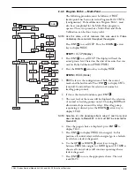
The microprocessor-based Sentinel offers all operator func-
tions and setup procedures from the three tactile-feedback
keys described above. Due to the number of user program-
mable features included in the unit, the calibration flow
chart is extensive. The flow chart is modular, however, it
can be divided into five subsections or program paths
which are connected to a home base, or normal operating
mode,
RUN
(walking
M
or
S
). When letters scroll horizon-
tally across the LED and no error messages are displayed,
all systems are functioning properly. The calibration flow
chart structure is shown on page 12.
NOTE: If MagneCal precalibration data was entered at the
factory, use Advanced Calibration procedures (
Section 2.5
) in
conjunction with the standard calibration procedures.
2.2
Program Paths
In order to properly calibrate the Sentinel, the Calibration
instructions are broken down into the five PATHS
described below.
Access to program paths is granted with the following
key strokes:
Configuration
Press
ENT
and
UP
arrow keys
simultaneously (
)
Single Point
Press
ENT
Probe Calibration
Press
UP
and
DOWN
arrow keys
simultaneously (
)
NOTE: This procedure MUST be performed if Multi-Point mode
is selected.
Multi-Point
Press
ENT
Service
Press
ENT
and
DOWN
arrow keys
simultaneously (
)
NOTE: At any given time during user configuration, pressing the
ENT
, UP
, and DOWN
arrow keys simultaneously
(
)
will escape from any location and return to
RUN
.
ENT
ENT
ENT
ENT
ENT
ENT
ENT
ENT
50-621 Kotron Sentinel Models 822, 832 and 842 RF Point Level Switches
11
Configuration
Multi-Point
Service
Probe
Calibration
Single Point
R
U
N


