1.0
Installation
This section provides detailed procedures for properly
installing the Model TK1 Liquid Level Switch.
Caution:
If equipment is used in a manner not specified by
manufacturer, protection provided by equipment may be
impaired.
1.1
Unpacking
Unpack the instrument carefully. Inspect all units for dam-
age. Report any concealed damage to the carrier within 24
hours. Ensure that all components have been removed from
the packing material. Check all contents against the packing
list and report any discrepancies to the factory. Check the
nameplate model number to ensure that it corresponds with
the packing slip and purchase order. Record the serial and
model numbers for future reference when ordering parts.
Model Number
Serial Number
1.2
Before You Begin
Caution:
During the installation of Model TK1, the float and pivot
area must be kept free of metallic particles that might be
attracted to the magnet.
Caution:
This instrument is intended for use in Installation Category
II
,
Pollution Degree 2.
1.2.1 Site Preparation
1. Ensure that the length and the inside diameter of the
mounting nozzle are sized correctly for the Model TK1.
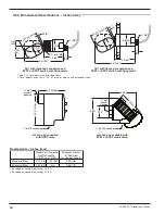
See dimensional information on page 10 for requirements.
2. Ensure that the mounting nozzle, coupling or flange is
within 3° of horizontal. If mounting the TK1 in an external
cage, ensure that the top/bottom piping is within 3° of ver-
tical in all directions.
1.2.2 Equipment and Tools
No special equipment or tools are required to install the
Model TK1 Liquid Level Switch. The following items are
recommended:
• Wrenches, gaskets and/or bolting as appropriate for the
process connection.
• Pipe wrench
• Level
44-608 TK1 Liquid Level Switch
3


