44-608 TK1 Liquid Level Switch
1.3
Mounting
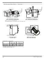
The Model TK1 Liquid Level Switch is available with a
1
1
⁄
2
" or 2" threaded mounting bushing as well as several
flange mountings.
1.3.1 Threaded Mounting
Apply either Teflon
®
tape or appropriate lubricant to
mounting threads to prevent galling. Engage thread by hand
to avoid damage. Using a pipe wrench, rotate the unit
clockwise until threads are tight in mounting. Ensure that
the N.O. marking on body is upward for normally opened
operation on models with SPST switches. For normally
closed operation, ensure that the N.C. marking is upward.
Models with SPDT or DPDT switches should be mounted
with the N.O. marking upward.
1.3.2 Flanged Mounting
Have proper flange bolting and gasket(s) on hand. Carefully
align the bolt holes of the TK1 flange with those of the
vessel mounting flange. Ensure that the N.O. marking on
body is upward for normally opened operation on models
with SPST switches. For normally closed operation, ensure
that the N.C. marking is upward. Models with SPDT or
DPDT switches should be mounted with the N.O. marking
upward. Ensure that the flange gasket is seated properly.
Install flange bolting.
Caution:
Operation of all buoyancy type level devices should be done
in such a way as to minimize the action of dynamic forces on
the float or displacer sensing element. Good practice for
reducing the likelihood of damage to the control is to equal-
ize pressure across the device very slowly.
1.4
Wiring
NOTE: A switch or circuit breaker shall be installed in close proximity to
equipment and within easy reach of operator. It shall be marked
as the disconnecting device for the equipment.
NOTE: For supply connections in installations with ambient tempera-
ture up to +70° C, use wire with a minimum rating of 75° C as
required by the process conditions. Installations with ambient
temperatures up to +80° C require wire with a minimum rating
of 85° C as required by the process conditions. Use a minimum
of 14 AWG wire for power and ground field wires.
1. SPST reed switch: Switch action is determined by the orien-
tation of the TK1. For actuation on rising level, ensure that
the TK1 is positioned so that the N.O. marking is on top.
For actuation on falling level, ensure that the TK1 is posi-
tioned with the N.C. marking on top.
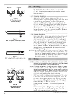
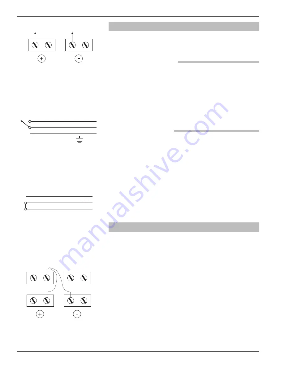
Connect wiring to terminals per the wiring diagram in
Figure 1.
Connect wiring to the flying leads per wiring diagram
in Figure 2 when mounted in N.O. position, and as in
Figure 3 when mounted in N.C. position.
4
Figure 1
SPST wiring diagram
terminal housing
Figure 4
SPDT wiring diagram
terminal housing
Figure 2
SPST wiring N.O. position flying leads
to switch
to switch
NO
NC
not used
C
to switch
Red
Green
Red
Figure 3
SPST wiring for N.C. position flying leads
Green
Red
Red


