11-1
11
11. AVM-510A Option T
(For Transmission Monitoring)
Introduction (AVM-510A-T)
This chapter describes the following functions added to the AVM-510A in the option
T:
•
Transmiter measurement set using zero carrier reference
•
1H line sweep of differential gain and differential phase
•
Incidental Carrier Phase Modulation (ICPM) display of transmitter phasing from I and Q outputs
of a broadcast quality demodulator
Transmitter Measurement Set
This section describes the following components in the transmitter measurement set:
•
Zero carrier
•
Measure line
•
Measure signal ID
Zero Carrier
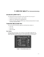
In the transmitter measurement set, the measurements for
PEAK VIDEO
,
WHITE BAR
, and
BLANKING LEVEL
are all referenced to a zero carrier reference pulse (see Figure 11-1). This
reference pulse must be in the vertical interval on any horizontal line from 9 to 25, inclusive.
Figure 11-1. Transmitter Measurement Set
Summary of Contents for MM-410
Page 16: ...About This Manual 1 4 Notes...
Page 34: ...Installation 4 6 Notes...
Page 48: ...Front Panel Operation 5 14 Notes...
Page 102: ...Viewing Waveforms Vectors and Pictures 7 30 Notes...
Page 126: ...Automatic Measurement AVM 510A 9 20 Notes...
Page 148: ...AVM 510A C For Component Measurements 12 4 Notes...
Page 158: ...Connector Pinouts B 4 Notes...
Page 162: ...Calibration D 2 Notes...


