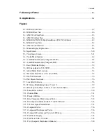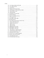
About This Manual
1-2
•
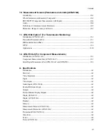
Chapter 11: AVM-510A Option T
(For Transmission Monitoring
)— Describes the functions
added to the AVM-510A using the option
T.
•
Chapter 12: AVM-510A-C
(For Component Measurements
)— Describes the component
measurement set and the digital measurement set when an SDM-550 is interconnected.
•
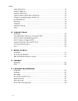
Appendix A: Specifications— Lists the MM-410/AVM-510A electrical and mechanical
specifications.
•
Appendix B: Connector Pinouts— Identifies and describes the pinouts of each connector on the
MM-410/AVM-510A.
•
Appendix C: Memory Locations — Lists the recommended memory locations for the MM-
410/AVM-510A.
•
Appendix D: Calibration— Explains how to access the Calibration menu options for the MM-
410/AVM-510A.
•
Appendix E: Command Codes (AVM-510A)— Describes the RS-232 protocol between the MM-
410/AVM-510A and a PC.
•
Appendix F: Glossary of Terms— Lists commonly used video and graphics terminology.
Conventions
Convention
Example
Description
Refer to
Italics are typically used for titles, menus, and references to other sections of
this manual or other manuals.
A:\setup
Monospaced text indicates a command that you need to enter to run an
application or utility.
Enter
Bold faced text indicates a key that must be pressed on a PC keyboard to
complete an action.
INPUT
Upper case text indicates an option from the Config or Msmt menu that has sub-
menu options under it when selected.
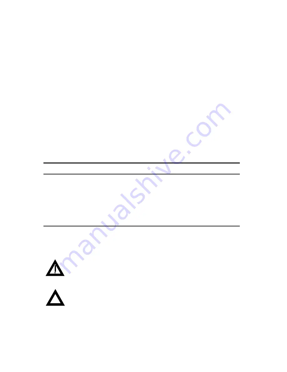
Special Notices
Two kinds of special notices are used in this Operator’s manual to emphasize specific information.
WARNING:
indicates the presence of a hazard that can cause personal injury if
the hazard is not avoided.
CAUTION:
indicates the presence of a hazard that might cause damage to
hardware or that might corrupt software.
Summary of Contents for MM-410
Page 16: ...About This Manual 1 4 Notes...
Page 34: ...Installation 4 6 Notes...
Page 48: ...Front Panel Operation 5 14 Notes...
Page 102: ...Viewing Waveforms Vectors and Pictures 7 30 Notes...
Page 126: ...Automatic Measurement AVM 510A 9 20 Notes...
Page 148: ...AVM 510A C For Component Measurements 12 4 Notes...
Page 158: ...Connector Pinouts B 4 Notes...
Page 162: ...Calibration D 2 Notes...


