AVM-510A Option T (For Transmission Monitoring)
11-8
Display Setup
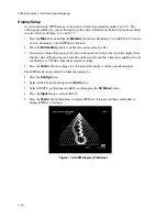
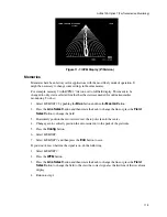
As stated previously, ICPM modes can be accessed via factory default memories 9 and 10. The
following procedures lets you set the display to the correct calibration if the I and Q signals are offset
in gain or level (see Figures 11-6 and 11-7).
1.
Press the
Blue
button and then the
Mesmnt
button to recall memory 9 with ICPM at 2
°
/division
or to recall memory 10 with ICPM at 6
°
/division.
2.
Move the
Horizontal
position to set the zero carrier point to center.
3.
If necessary, change the gain to set the zero carrier point vertically to the top of the display. Note
that the value of the phasing can be read from the graticule and that a line select might need to be
enabled to see a VIT line when the transmitter is online.
4.
Press the
Vector
button to change to 6
°
/division if the display is off the screen hoizontally.
The ICPM mode can be selected without the memory by:
1.
Press the
Config
button.
2.
Select
INPUTS
and and then press the
Entr
button.
3.
Select
B INPUT
, set the format to
BETA
, and then press the
Clr Menu
button.
4.
Press the
Input
button to select
B INPUT
.
5.
Press the
Vector
button three times to display ICPM at 2
°
/division and then a fourth time to
display ICPM at 6
°
/division.
Figure 11-6. ICPM Display (2
°°°°
/Division)
Summary of Contents for MM-410
Page 16: ...About This Manual 1 4 Notes...
Page 34: ...Installation 4 6 Notes...
Page 48: ...Front Panel Operation 5 14 Notes...
Page 102: ...Viewing Waveforms Vectors and Pictures 7 30 Notes...
Page 126: ...Automatic Measurement AVM 510A 9 20 Notes...
Page 148: ...AVM 510A C For Component Measurements 12 4 Notes...
Page 158: ...Connector Pinouts B 4 Notes...
Page 162: ...Calibration D 2 Notes...

